Werkgroep “Stoom in de Cruquius”
MAIN ENGINE STATUS REPORT September 24, 2002
Jan A. Verbruggen
Contents
Note on edition
Note on the Cornish engine cycle
Note on engineering reference documents
Note on the ‘state to restore to’
1. Power source
1.1 Steam
1.2 Air
1.3 Electric drive
1.4 Hydraulic drive
2. Building and engine foundations
2.1. Basement and foundations
2.2. Cylinder holding down bolts
2.3. Columns and tension rods
2.4. Collar launder
3. Hydraulic
3.1. Plungers and plunger housings
3.2. Check valves
3.3. Bypass valve and governor
3.4. Standpipes
3.5. Piping
3.6. Hydrostatic test (water hydraulics operation only)
3.7. Filling and draining (water hydraulics operation only)
3.8. Vertical guides and the risk of binding
4. Steam cylinder
4.1. Moving the piston up and down
4.2. Pistons
4.3. Piston rods
5. Miscellaneous parts
6. Weight
6.1 General discussion
6.2 Weight removal
6.3 Bearing overhaul
7. Beams
8. Outdoor pumps
9. Valve gear
10. Working life : operational aspects
10.1. Principal engine data
10.2. Design capacity
10.3. Efficiency or duty
10.4. Stroke length control
10.5. Adjusting to varying load
10.6. Starting
10.7. The film sequence
10.8. An eyewitness account
10.9. What happened on 14 January 1851?
11. Cautionary notes for future steam enthusiasts
Acknowledgements
References
Note on edition
This report supersedes the December 18, 2001 version. Nontrivial changes are in red. It has been prepared in English to facilitate international discussion.
The project was essentially completed when the engine was officially restored to motion at an inauguration ceremony on 4 June 2002. As a consequence, this status report is now finalized; future changes will mainly correct errors or clarify aspects.
No apology is made for the length of the report. It is intended as a coherent record and – judging from past experience – future generations are more likely to find it lacking in detail than anything else …..
Summary
The Cruquius engine stopped working in November 1932. On 10 June 1933 she was steamed one last time, for a closing and preservation ceremony. In March 1982 the Cruquius Trust council agreed to establish a working group to study the feasibility of making the engine move again. First of all, various ways to drive the engine were compared. It was decided to attempt hydraulic drive. Next, a number of aspects of the building and engine were investigated to see if these would permit motion. In a number of cases this entailed quite extensive cleaning or dismantling operations.
All activities and findings were fairly extensively recorded, both photographically and in writing. This report is primarily the written record of the investigating, cleaning, repair, and restoration activities. Most details of the hydraulic project will eventually be the subject of a separate document.
Note on the Cornish engine cycle
It is assumed that the reader has some knowledge of how a Cornish engine works, so the following account is kept very brief. A Cornish engine is a single-acting nonrotative vertical steam engine, in which steam and vacuum lift a dead weight during the first half of the stroke. During the second half of the stroke the steam piston is in equilibrium (i.e. the spaces on both sides communicate via the open equilibrium valve) and the weight descends, using its gravitational energy to operate the pumps. In the most widespread type of Cornish engine, widely used for mine drainage, the steam cylinder and the weight are at opposite ends of a rocking beam or bob. The weight (consisting mostly of the pump rod hanging down a deep shaft) is at the beam’s “outdoor” end and is pulled up by admitting steam above the piston at the other end (indoor or steam stroke). During the following outdoor or equilibrium stroke the descending weight pushes down the plungers of force pumps which, in a mine, are arranged in series for additive lifts.
Cruquius has lift (bucket) pumps in parallel for additive capacity, and the weight must pull their pistons up; consequently it is at the indoor end of the beams, above the steam cylinder. To lift the weight, steam must now be admitted under the piston, i.e. the engine is inverted. Another peculiarity of this engine is, that there are two cylinders: a 213 cm (84″) HP cylinder built inside a 366 cm (144″) annular LP one. During the ‘equilibrium’ stroke only the HP piston is actually in equilibrium; the downward pressure differential on the LP piston is added to the gravity action of the weight. Because the steam expands in two stages, this is a combined or compound engine and, strictly speaking, no longer fully single acting [1].
Note on engineering reference documents
In the course of the preliminary studies in the early 1840’s, the consultants Gibbs & Dean produced 25 drawings, most of which survive in the polder archives; these are historically important, but certainly not representative of the Cruquius engine as built.
In 1988 P. van Putten found an incomplete set of ‘contract drawings’ for Cruquius and Lynden in the polder archives. These had probably been made by the consultants, and the manufacturers (Harvey, Fox and van Vlissingen) would probably have produced their own shop drawings. Nevertheless, these contract drawings – which show signs of heavy use – are undoubtedly a close approximation of the Cruquius as built. They confirmed many observations made during recent inspections, and they revealed several hitherto unknown details.
After the Harvey & Co. works in Hayle (Cornwall) closed in the last quarter of the 19th century, the drawing office seems to have been left largely undisturbed until its contents (including many drawings) were destroyed in the 1950’s. It must be assumed, that workshop drawings of Cruquius no longer exist.
In 1988 A.J. Engel found a little notebook [2] with operating and maintenance notes for the period 1924-1932. The polder archives may hold more similar notes.
Note on the ‘state to restore to’
At the outset of restoration work of any kind this is an important question. Any object has a history of modifications, and so it has existed in more than one state. One of these must usually be selected as a basis for restoration. Fortunately, for Cruquius the choice is easy. Modifications to the engine have been few and minor. Issues such as “Should we reconnect the 8th pump ?” or “Will we shift the steam slide back to its original position ?” are not fundamental. The only major changes occurred in the boiler house: two wings added in 1860, full reboilering in 1888/1890, cleared out c.1936. Restoring the boiler house to any of the states prior to 1936 is virtually out of the question, so here the selection problem is largely academic.
1. Power source
Four alternatives were considered: steam, compressed air, hydraulic and electric drive. Each of these is discussed below. Eventually modern mineral oil hydraulics (see 1.4.2) was chosen.
1.1 Steam
This would obviously be historically ideal, technically attractive, and spectacular. It would also mean installing a substantial steam supply, restoring all parts of the engine to full working order, and the need for qualified (and probably paid) operating and maintenance staff. Apart from the steam supply, major hurdles would be the soft piston packings, the piston rods and (possibly) the entire condenser. The cost – both initial outlay and annual operating expenses – would be very high, and there would be serious space problems as well: how can a steam supply be housed, without sacrificing a substantial part of the museum space, in a way acceptable from preservation, museum, engineering and planning viewpoints ?
Would non-condensing operation be feasible? Possibly, but it would mean exhausting to the atmosphere, i.e. making a hole in the condenser and a pipe from there to outside the house, a modification which – apart from being impractical and unsightly – would unacceptably damage the engine. Occasional steaming, as practised at several steam museums, would necessitate addressing the problem of conservation during idle periods, e.g. by filling the system with nitrogen. Driving a Cornish engine is a highly skilled job, mistakes can seriously damage the engine and building. Training facilities for Cornish engines are not available in Holland; a course at Kew Bridge Steam Museum in London would appear to be the only possibility. For occasional steaming, at least two or three fully qualified drivers would have to be available.
As a consequence, steam is considered not to be a realistic short or intermediate term goal. However, an important touchstone for any other solution must be, that it not block the way for possible future steam plans. Some measures had to be taken, and modifications made, which would have to be undone if steam operation were to be attempted in future. These are listed in Sect. 11.
Additional note 1998/1999 about steam supply. In view of recent discussions and challenges, some aspects of the steam supply may be further elaborated.
Like most Cornish pumping engines, Cruquius worked at stroke rates of a few up to seven or eight per minute, at steam (gauge) pressures in the 2 to 4 bar range. Steam was wet or saturated (certainly not superheated), at c.140-160 °C. Steam would be admitted only during the steam half-stroke, for about one second, i.e. for about 10% of the ten-second full-stroke duration (at six strokes/minute). In the Cruquius engine the quantity of steam admitted would originally have been c.50% of the HP or central cylinder volume, later almost doubled. For this later case, the average steam consumption of Cruquius has been estimated at c.7 to 10 tons per hour, as a consequence the peak rate would be about 70-100 t/h. Steam was supplied by coal-fired boilers of the Cornish or Lancashire type: 1849 six Cornish, c.1860 ten Cornish, 1888 six larger Lancashire. These boilers have a large water space. Their combined steam space is also considerable – a rough estimate would be 70-80 m3 – providing some buffering for the irregular steam consumption, but not enough. Over the boilers, occupying the full width of the boiler house was a steam receiver of c.2 m diameter, roughly doubling the buffering capacity. Even so, the strokes of the engine were reputedly reflected in level fluctuations in the boilers’ water gauges.
The final set of boilers was removed c.1935; only vestiges of their foundations remain. The boiler house was eventually converted to museum space.
Re-creating a close approximation to the original (1849, 1860 or 1888?) steam supply would mean moving the museum elsewhere. Obtaining a suitable set of boilers second-hand is out of the question. New boilers would have to be made, their design necessarily a compromise between “old” appearance and modern safety requirements.
Forget about recreating a 19th-century boiler house, then, and supply steam with modern boilers? Such boilers are more compact, and they invariably have much higher pressure, e.g. 15-40 bar. Special throttling valves can reduce pressure, but the result would be superheated steam at temperatures unsuitable for a Cornish engine (packing, gaskets, condenser etc.). Steam conditioning by water injection is probably possible (special – and expensive – reducing valves). The irregularity problem could most likely be solved by adding an immense steam accumulator (c.50 m3 would appear to be a minimum). A modest-sized boiler and reducing valve would then suffice, but the space needed for the entire steam plant would be huge. As an aside, it may be noted that a type of accumulator exists, which stores steam in the form of pressurized water at boiling point. This is much smaller, but only suitable for highly fluctuating steam input and fairly constant output – just the reverse of what is needed here.
The steam supply alternatives discussed above, all appear to be technically feasible (but each would need considerable further study). Other aspects, such as planning and cost, are much more problematic.
1.2 Air
Air has similar supply and space problems. An advantage would appear to be, that a fully functional condenser is not needed, but – as for non-condensing steam – a substantial exhaust would have to be made. It might be considered to release the exhaust air indoors, and then one way to do this might be to remove one or both covers on the connecting ducts between the condenser and air pump barrels (in the condenser cistern; these covers provide maintenance access to condenser foot valves). Apart from the condenser, however, all engine parts must be restored to full working order, as for steam. P. Stokes [3] has proposed the use of vacuum via the exhaust. Conceivably, a vacuum pump could be connected to one of these foot valve access openings. This would create different (but not easier) space problems. Otherwise such vacuum operation would not differ much from the use of low-pressure compressed air. The relative merits of air and vacuum might be analyzed via computer simulation (which may one day become available).
There is one Cornish engine which is occasionally operated on air for the public : Parkandillick engine near St. Austell, Cornwall. This 1,26 m (50″) engine pumped china clay slurry from a rather shallow shaft, using an outdoor bucket (lift) pump. This mode of operation, where the steam stroke is also the power stroke of the pump, differs fundamentally from the more usual “steam lifts weight, weight operates pump” mode. The (outdoor) surplus weight on this engine serves mainly to return the pump and steam pistons, and consequently it is much less than on a mine pumping engine.- there was even a balance bob to partly compensate for the excess pump rod plus piston weight. This balance bob has been removed, and the pump rod cut, leaving an outdoor weight surplus of c.4 tons. The Parkandillick engine now runs quite well on air of very low pressure (c.0.3 bar or 4 psi). The speed can be reasonably realistic, because the moving mass is now quite low. This or a similar approach does not appear feasible for Cruquius.
1.3 Electric drive
An electromechanical drive to a reasonably central point does not appear to be possible without unacceptably destructive intervention (such as making a big hole in the double cylinder bottom). An advantage would be, that engine components would not have to be fully functional or tight, just movable.
1.4 Hydraulic drive
Hydraulics with standard components offers the same advantage, and requires less space than an electric drive for the actual drive components (cylinders), and there is considerable freedom in the location of the power pack and associated components. Finding a suitable and not-too-conspicuous location for the long drive cylinders would be quite a problem, however. It has been suggested that they be concealed in the outdoor pump barrels; other considerations apart, however, these are standing directly on the wooden foundation floor (see Sect.2.1), and cannot take the required upward force. Therefore two other possibilities have been considered.
1.4.1
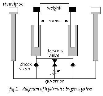
Use part of the existing passive hydraulic (buffer) system, see fig.1. This subsystem was installed to prevent shock due to uncontrolled closing of the water pump bucket valves at the end of the steam stroke when the weight has reached its top position. This position is ‘locked’ for a suitable period (a couple of seconds) to allow the bucket valves to close. During the up (steam) stroke, two 225 mm (9″) dia. plungers or rams, attached to the ears of the central weight, draw water from standpipes via check valves. The water column locks the weight in its top position until a bypass valve is opened simultaneously with the engine’s equilibrium valve. A butterfly type governor valve in the bypass connection may have aided control of the equilibrium stroke speed. This valve is now fully open, and its operating control was removed long ago (see also Sect.3.3 and Sect.10).
If this system could be connected to a (water) hydraulic power source via nozzles to be made on the HP and LP connecting pipes, it might be possible to use the existing plungers to move the engine. The plungers would have to be fully operational and all hydraulic joints and packings would have to be tight. The existing hydraulic valves would have to be secured in their closed positions and made reasonably tight. Closing shut-off valves on the nozzles, and freeing the check and bypass valves, would restore the original situation and enable the system to be used for its original purpose, e.g. in a future steam scheme.
1.4.2
Mount standard hydraulic cylinders “parallel” to the buffer rams, i.e. between the engine foundation and the weight ears, and use standard mineral oil hydraulics.
Much effort has been put into investigating the water hydraulics scheme, and the findings have been extensively recorded. Eventually, and partly due to the problems envisaged, this idea was abandoned in favour of mineral oil hydraulics. The design etc. of this solution is documented elsewhere.
2. Building and engine foundations
2.1. Basement and foundations
The 1846 building specification called for the engine building basement to be constructed as a dry tub with bottom and walls executed as watertight masonry (brick in tarras mortar).
The entire building structure rests on pile foundations at two levels: the boiler house / exit channel level (high, not further discussed), and the engine-house / pump / chimney stack / retaining wall level (low). The tops of the piles are coupled by a massive timber grid: capping beams (running E-W, or parallel to the polder dike, Dutch kespen) link the tenoned top ends of the piles, N-S running grating beams (Dutch kloosterhouten or schuifhouten) are cross-cogged to the capping beams and link them to form a sturdy grid (note: the terms in various dictionaries differ). Between these grating beams a 10 cm thick floor is laid in two layers on the capping beams, about 1.5 m below polder level. All masonry rests on this floor. The density of the piles (and of the coupling grid) is increased where the loads are heaviest, i.e. under the central engine house and the chimney stack, and under the eight outdoor pumps. Here, also, the timber structure is part oak, the remainder being pine.
From the illustrations in [17] it would appear that the height of the grating beams exceeds the floor thickness, i.e. those beams would stand proud of the floor, and where these “ridges” interfere with the pump supports (lantern pieces, see Sect.8) the grating beam top portion would be cut away. The building specification is not fully clear on this, close inspection in connection with work on the pumps (see Sect.8) does indeed reveal the ridges.
The brick floor of the lower engine house basement is c.0.5 m thick, and is thus about 1 m below polder level. On this floor stands the central engine foundation block with inspection access to the bottom ends of various anchor bolts via tunnels (see Sect.2.2). This c.5 m tall brick pedestal is of oblong shape and is covered by a stone slab (in several pieces) which is the cylinder loading or bedstone. At the long ends recesses have been left to mount the hydraulic plunger housings abt. 1 m lower than the cylinder. The space in these recesses between the housings and the main block was later largely filled with brick masonry; this was much deteriorated and the original shape and purpose of this brick infill can only be guessed at (see Sect.3.1). Most of it has been removed for inspection of the plunger housings.
The oblong pedestal stands within the circular engine house wall and leaves two large and two smaller crescent-shaped basement sections; one of the large ones is largely occupied by the condenser cistern, which is supported by three brick connecting walls. The space between these appears to be inaccessible.
In 1983 the other three basement sections were found to be largely filled with ‘rubbish’, which turned out to be mainly a thin black mud drying to dark grey. About 1 m above polder level an overflow hole in the outer wall was found. The ‘dry tub’ had apparently become a rubbish dump and a water collecting basin, where everything up to the overflow level was immersed in (somewhat corrosive) mud. As a result access to the inspection tunnels was blocked, and even the position of the entrance to these tunnels could no longer be located.
In 1985 volunteers removed, bucket by bucket, about ten m3 of mud and rubbish, and uncovered the inspection tunnels. Very few objects were found: a small elliptical cast iron weight which used to keep the equilibrium pipe drain cock normally closed, a larger one for a long-disused spindle lever on the hydraulic valve body (see Sect.3.3 for details), a spanner, a glass bottle, fragments of gaskets, shoes etc.
The following sequence of events appears likely:
- 1848/1849 the steam-jacketed cylinder is externally insulated. This insulation is not specifically described in the building specification, but as mentioned in [4] it is similar to the steam collector insulation, which is specified as a layer of dry, graded peat-ashes in a wooden outer casing. An estimated 7,5 m3 of ashes would be required.
- The steam jacket consists of a number of cast iron segments, connected to each other and to flanges on the cylinder casting by bolted and iron-cemented flange joints. It is known from Cornish practice, that these rigid jacket arrangements were difficult to keep tight, and that after some years the only practical solution often was to disconnect the steam jacket, and to put up with reduced efficiency. This is highly likely to have happened at Cruquius, sometime between about 1860 and 1890. Maybe the polder archives will one day yield more specific dates. The jacket supply pipe is gone, and its takeoff connection on the vertical steam pipe blanked off. Some of the interconnecting piping was cut; one remaining tube nozzle was found to be plugged with cotton waste from the inside. Fig.356 in [5], taken c.1906, shows the steam jacket without outer insulation. These observations confirm that the jacket was disconnected at a time when the engine was still in regular use.
- Around 1890 extensive repairs appear to have been carried out, possibly including the removal of the wooden outer casing – by then probably already derelict. The ashes were conveniently swept into the basement. Drains were rearranged to discharge into the basement (this probably necessitated the overflow hole). Later, even a rainpipe was routed to do the same ! (see Sect.3.3 ).
Nothing has yet come to light to ascribe these events to anything but technical ignorance. It should be borne in mind that the mechanical engineering staff of even a large polder such as Haarlemmermeer was minimal.
R.L. Hills has commented [6], that the steam jacket could not do much for the central HP cylinder anyway, so that its beneficial effect was at best marginal, and disconnecting would not have had much detrimental effect on efficiency.
The drains no longer operate, and the rainpipe has now been rerouted. To make the basement once more the ‘dry tub’ it was designed to be, all that needs to be done is to close two cracks in the basement wall at the North (canal or boiler house) side, through which some water still seeps. Final cleaning could then be carried out.
2.2. Cylinder holding down bolts
The cylinder foundation is an oblong block of brick masonry about 4 m high, capped by a 0,4 m thick stone slab (built up of several pieces) measuring about 4,5 by 6 m overall. The complex cylinder bottom casting (with steam jacket space, and steam and equilibrium conduits) rests on this loading. At its outer circumference this carries the LP cylinder, the double bottom flange of which is held down by thirteen wrought iron 1-1/2″ bolts of about 4,5 m long. The HP-LP separating wall is secured by four similar bolts. The latter would seem to be rather light anchoring for an engine this size, but it should be remembered that this is an inverted engine where the working load on the cylinder foundation is always downward (the permanent condenser vacuum under the annular piston tends to pull the bottom up, but the weight of the cylinder-plus-covers by itself is more). On the same grounds, frequent inspection and retightening of these bolts seems less essential than in Cornish practice. Some of the bolts are hidden, e.g. between the cylinder and the condenser cistern, and are not accessible for maintenance or retightening. All bolts extend down through cast iron plates embedded in the masonry. At their bottom ends they are fitted with cotters, at the top they are tightened with nuts. Under the LP bolts is an annular inspection tunnel approx. 1,1 m high and 0,6 m wide. The HP bolts are in recesses in the central cylindrical inspection space of about 1,6 m diameter which extends over the full height of the foundation block. It is not possible to replace them with the cylinder in place. Clearly the designer intended the bolts to last the life of the engine. The foundation block itself is built on a 0,5 m thick brick floor, which rests on the wooden pile foundation structure.
Due to the circumstances described in Sect. 2.1 the water/mud level in the basement had blocked access to the inspection spaces, and had immersed the bottom half meter or so of the bolts, since about 1890. It was not surprising to find, after the cleanout operation, two corroded anchor bolt bottom ends standing on the floor of the inspection tunnel. As it was not possible to assess the condition of the other eleven with certainty, it was decided for safety reasons to remove as many as possible. The top ends were cut (oxyacetylene), the bolt was forced down, and meter after meter was cut off in the tunnel. The top ends of the 3 bolts at the south side are behind the condenser cistern and thus inaccessible for cutting. All that could be done here was hammering and trying to pry loose the bottom end, to try and make sure that the bolt was still hanging by more than a ‘hair’.
Eventually some or all of the anchor bolts will have to be replaced; a suitable method appears to be: use 1 m lengths of standard threaded rod with coupling muffs not exceeding 1 1/4″ dia., build these upward from the inspection tunnel and fit them with replica top and bottom ends. Commercially available M24 rods and muffs appear suitable. Strength is not an important issue, and modern bolt/rod materials such as 8.8 are far stronger than wrought iron anyway.
2.3. Columns and tension rods
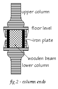
The cylinder foundation block carries two pairs of cast iron columns (see fig. 2) which support the two main beams at the cylinder floor level, plus upper columns. Between each pair, the wooden beam is reinforced by two iron plates. This reinforced section supports the cast iron pedestal which carries the crosshead (weight cap) parallel guide rods and holds the lower buffer stop. The lower columns are pre-compressed by 125 mm (5″) dia. tension rods which run from this pedestal down into the foundation block. Their cottered bottom ends – now rather corroded – are in recesses in the outer wall of the inspection tunnel.
A detailed assessment of the condition of these tension rods has not been made, as they seem not to be overly important for the engine operation envisaged.
As fig. 2 shows, the column ends are ‘cradle’-shaped. At the cylinder floor level, however, most of the cradle sides are broken off; at the southeast column a repair with clamps and straps has been carried out, elsewhere nothing was done. The damage would appear to have been caused by severe shocks. Overstroking comes to mind (see the remarks in Sect.9 about starting problems to be expected for a late cutoff engine), but vertical jolts would have to be violent indeed, to cause fractures in these places. See Sect.10.9 for the likely cause.
2.4. Collar launder
The outdoor pumps (see Sect.8) stand on the foundation floor (see Sect.2.1), their upper portions protruding through a 10 cm (4”) thick oak floor, which is the bottom of a launder running around the pump side of the engine building. This collar launder, connects to two channels running to the front of the building and through the dike into the encircling canal of the polder. The pumps discharge onto this collar launder, where the level is normally the same as in the canal, i.e. c.1.5 m (5ft) above the floor. The potential breach in the dike – which might cause canal water to flow back into the polder in case of a serious structural collapse – is secured by two sets of automatic sluicegates at the junctions between collar launder and channels. One gate of each set has a paddle, and can also be latched in the open position. We reckon this provision probably served two purposes:
- Using the paddles to fill the collar launder at the start of a pumping campaign, in order to prime the pumps.
- Water inlet in times of drought; this is made plausible by the specification requirement of three hinged hatches in the collar launder floor, which would permit water to be discharged into the polder. The paddles would be used to equalize levels, after which one gate of each set could be latched open to increase flow.
The collar launder floor, which had deteriorated rapidly after the closing down of the pumping station, has been restored in simplified form, without hatches, with reduced thickness (8 cm) and fewer supports, allowing water-filling it to a depth of c.50 cm (20”). One of the quite badly deteriorated paddled gates has been removed and cut up, with the intention of discarding it. Volunteers have rescued the seriously damaged remains, and are currently restoring this gate. It should be noted, that the discharge channel to the outside canal was largely filled in, as a safety measure after Cruquius had been decommissioned in 1932, so the sluices can no longer perform their function.
3. Hydraulic
Note: much of this Section resulted from the investigation of the feasibility of water hydraulic drive (see Sect.1.4.1). The later decision in favour of oil hydraulics results in many of these findings and observations now having mainly historical interest, and less practical value for restoration.
The purpose and operation of the hydraulic has been explained in Sect.1.4.1. In the operational period the static pressure in the system would be about 80 bar (assuming a weight of 65 tons); peaks of about 120 bar have reputedly been observed. By reducing the load, it should be possible to move the engine with a pressure of less than 50 bar (note that a Cornish engine cannot be operated with zero load). In the course of the activities discussed below, the entire hydraulic system has been high pressure jet cleaned by the firm of Groenheide. Evidently the system can never be as clean as a modern hydraulic system has to be.
3.1. Plungers and plunger housings
For water hydraulic drive, the 225 mm (9″) dia. plungers must be fully functional. A first endoscopic inspection via the air relief cock, just below the stuffing box, revealed a surface that is somewhat rough, but not seriously corroded. Surface inspection with a microscope confirmed the material to be cast iron. The surface is rather hard, but the coherence of the grains has deteriorated in places, as chips can be chiselled off with surprising ease.
The two-tier bronze junk rings were easily lifted, but the bronze stuffing boxes could not be removed from the tops of the housings: the 6 radial fixing screws resisted all attempts (brute force, penetrating oil, heat) at removal; one bolt on the east housing eventually fractured. Subsequently the stuffing boxes were emptied, partly because it was hoped to create enough swing at the top for lifting out the 1 ton cast iron plunger at an angle (some 35 cm swing would be needed). The approx. 15 mm wide stuffing chamber yielded mainly tightly compressed braided hemp and asbestos fabric. A few layers further down, strips of leather were found. At a depth of about 140 mm a cup-shaped sheet brass ring rested on two more brass rings. These three metal rings were split; the two halves of the bottom one were interlocked, the second ring was held together by soft copper wire in a circumferential groove, locating pins on the top surface of this ring held the sheet ring halves in place.
The bottom of the stuffing box slopes inward. This indicates, that initially there were no bottom rings. The first ring is shaped to fit this sloping bottom. According to [2] ‘the worn bottom rings were filed flat and two 1/8″ brass ring halves fitted on top’ in 1924.
These plunger packings, which had to seal against about 100-120 bar (1400-1700 psi) water pressure, probably constituted one of the major maintenance and repair problems of the engine. The notes in [2] show that, even during the standby period, experiments with packing materials and arrangements were still being carried out. It is somewhat surprising that for a plunger with fairly rapid motion at high (cold) water pressure a hemp stuffing box should have been chosen. Hydraulic machinery – often working at similar water pressures – had been using leather cup packings from the start (Joseph Bramah, c.1795), building on pumping practice of at least 60 years standing [7]. The cup seal had proven reliability, did not require frequent retightening, and according to textbook sources friction amounted to as little as one fifth of that of a stuffing box seal.
For the time being, modern soft packing has been fitted, but if water hydraulic operation should turn out to be feasible, modern equivalents of the cup seal should be considered.
Each plunger has an axial hole in its top end to receive a wrought iron bolt, fixed with cotters. This bolt passes through a hole in one of the weight cap ears, and at the top a ‘head’ is formed by a ring secured with cotters. Both plungers were disconnected from the bolts and lowered. The east bolt had been sealed so well, that portions of its surface looked as if machined only yesterday. The swing obtained at the top was only about 1 cm, however. After raising the weight to its top position (see Sect. 4.1), the increased exposed length (and correspondingly reduced length in the housing), still allowed only about 5 cm sideways movement. This means that the plunger cannot be lifted out and that it will have to be cleaned and dressed in place as far down as practicable; for water hydraulic drive this implies a stroke shortening of about 20 cm to keep the remaining rough parts of the surface below the stuffing box.
Most of the visible plunger surface is fairly smooth, with slight and quite evenly spread pitting, but with the remainder of the original surface substantially intact. The diameter varies slightly over the length (about 1 mm), but the variations are very gradual; no circumferential ridges or steps are observed. The obvious cause is wear.
Two diametrically opposed faintly discernible ridges extend the full length and remind one of casting lines. This would be surprising, as these plungers were surely machined after casting? The portion which was in the stuffing box when parked, shows circumferential areas of heavier pitting.
Near the lower end, both plungers have a number of longitudinal ‘furrows’ of varying length and depth. The largest is a few mm deep, about 1 cm wide and some 60 cm long. Their cross section is rounded, and in some the deepest part has a rough surface. The most likely cause of these furrows is erosion by water spurting through packing flaws during the short period at the end of the steam stroke, when the hydraulic is under high pressure (80 bar or more). (In [8] problems with longitudinal grooves are mentioned for the large cast iron rams of the Anderton boat lift in the 1880’s; a report ascribed these to electrochemical causes.)
Repair is essential to avoid excessive stroke shortening. Three methods have been discussed:
- filling with a suitable plastic/steel compound; it is uncertain if this will stay put in the long run, unless the grooves are machined to a retaining (dovetail) shape, which is very awkward to do in place.
- welding; for cast iron this is quite difficult, and even with the best of precautions remains risky; if successful, it is very good.
- flame spraying; this requires careful preparation (cleaning) and control to achieve good adhesion, but the risks are small, there is little heating and no preparatory machining is needed.
Regardless of the method chosen, substantial surface dressing would be required afterwards.
Flame spraying was chosen, and was performed by the firms of Metco and Griekspoor using a high-nickel compound with chrome and moly. Subsequent dressing was done by volunteers, mainly by filing, using a three point bridge gauge set on an undamaged portion. The compound turned out to be not too hard, but very tough and difficult to file. Filing sounds like anathema for high pressure hydraulic parts, but in this case there seemed to be no other option short of dismantling the entire weight structure. The results appear to be no worse than the undamaged areas. Remaining minor cracks and blemishes were filled with ‘liquid steel’ epoxy, and dressed.
The surface is far from ideal by modern hydraulic standards; in addition there is a slight alignment error which manifests itself by 1-2 mm lateral movement of the ram in the gland over the stroke length. The following measures have been discussed. These may be combined, and they are relevant only for direct use of the water hydraulic system as discussed in Sect.1.4.1.
3.1.1 Resurface the rams by metallizing, by plating, or by fitting a sleeve. The latter might conceivably be done in situ, although this has not been thought through in every detail, and may present unforeseen problems. Removal of the rams to a workshop is to be preferred, and this involves either dismantling of much of the superstructure, or cutting and rejoining the rams. The latter appears technically feasible.
3.1.2 Re-alignment of ram and housing would involve extensive dismantling (i.e. disconnect, remove and re-align both the rams and their housings), or fitting a seal which can absorb the lateral motion.
The housings have a 60 mm thick bottom flange, with a 150 mm (6″) thick cover bolted on. The bolts have square heads which fit flush in square holes in the cover, with square nuts at the top. At least one of the bolts is missing. The force to be withstood by this connection is the hydraulic pressure acting on the narrow (5 mm) ring gap between plunger and housing, minus the weight of the housing, plus the stuffing box friction. A crude estimate would be 50 to 100 kN.
There are signs of corrosion everywhere, but mainly at the west side. The lower half meter or so of the housing has lost about 10 mm wall thickness; the 5″ tension rods are quite heavily corroded; the covers of the check valve housings are full of fairly deep valleys. Only pyramid-shaped vestiges remain of many of the bottom cover nuts. Water from the plunger stuffing box probably gushed all over, and the brick masonry infill discussed in Sect. 2.1 would provide some protection for the housings and tension rods by deflecting the water to the basement. From the film sequence data (Sect. 10.7) the total leak rate of the hydraulic system during the locking period can be very crudely estimated at 100 litres (20 gallons) per minute, or the equivalent of six powerful home showers. Of course, the locking period would last for only two to three seconds, but still some 5 litres (1 gallon) per stroke would leak from the system at each stroke.
3.2. Check valves
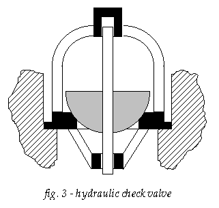
The two check valves shown in fig.1 are in fact two dual valves. Contemporary illustrations do not show these in much detail; some give the impression of a simple ‘ball-in-cone’ arrangement. The east valve body looks different from the west one: cover shape, casting surface, nuts etc., and it is less corroded. This valve has obviously been replaced (see Sect.10.9).
Both dual valves were dismantled; the valves are hemispherical and mounted on stems guided in bushings above and below (see fig.3). All internals are of bronze. The covers are fitted with a rubbery compound about 5 mm thick, probably an early form of liquid gasket. Why so thick ? The flange and cover have mating grooves and ridges, suggestive of a thinner gasket more suitable for high pressure. The answer may lie in the way the internals are kept in place. The cage with the top stem guide was pressed down by a central bolt in the cover. This screwdown is an eyebolt which thus doubled as a lifting eye. A locknut with a gasket washer secured the adjustment. This gasket could not, however, prevent water entering the thread gap from inside. Any further adjustment soon became impossible. Maintenance work may have altered the position of the top guide (e.g. renewal of seat); maybe the thick gasket simply bridged an adjustment gap which the bolt could no longer manage.
For hydraulic drive these valves are not needed, and for water-hydraulics they should be permanently closed. Minor leakage would seem acceptable, but even that could be avoided by fixing the valves to their seats with some easy-to-remove glue or liquid gasket compound. The seating surfaces of three of the valves and of all four seats are in good condition; there is evidence of repeated grinding and occasional trueing up. The seating surface of the fourth (northwest) valve is severely pitted. It is difficult to say if this is due to corrosion or to cavitation. It is surprising that the corresponding seat is perfectly smooth. After careful cleaning the pitted surface was filled with epoxy. This would not be suitable for normal operation, but it will hopefully do for a static seal.
The valve seats have an external rim to position the upper stem guide cage (see fig.3). There is thus a channel around the seat which, after the cleaning operation, held some water. After a few days the water had to be cleared out of three of the channels; the SW one was dry, so the fit of the seat in the housing had to be leaky. After careful cleaning, this was treated with a thin Loctite which would hopefully penetrate the (invisible and obviously narrow) gap. The channel will now hold water. The NW valve developed similar problems when the pressure was first raised to 40 bar, probably as rust and dirt were blown from an existing crack. The same remedy was applied.
The southwest housing has a crack in the gasket seating surface, which would probably cause leakage (and would have done so in the past); this was also treated with Loctite.
Surprisingly, the southwest cage ring had to be enlarged slightly (by filing) to fit around the corresponding valve seat. This cannot have been caused by corrosion, and exchanging the northwest and southwest cages only made matters worse. No explanation has been found.
The valves have now been re-assembled with elastic plugs (made of reinforced rubber hose) between valve stem top and guide end, and between guide cage and cover; these will not keep the valve shut against pressure, but they will assist the assembly process, at least while the liquid gasket is setting.
3.3. Bypass valve and governor
This is a valve assembly in two parts. The upper part of the housing connects the two branches of the HP connecting pipe and contains the bypass valve. To this is flanged the lower part which connects the LP branches, and contains the butterfly governor valve. The bottom is a flat cover bolted to a flange; at the center of this cover is a hole, surrounded by four screwed-in studs and vestiges of a gasket. As this is the lowest point of the hydraulic, this was probably the drain connection. The drain cock (no doubt discharging into the basement, see Sect. 2.1) is gone, probably removed when – some time after 1933 – rainpipes were arranged to discharge into the standpipes. As a result, rainwater from the roof, rich in oxygen and lately in acid, flowed via the LP pipes of the hydraulic into the basement and thence via the overflow hole in the wall to the polder outside. This detour has been rectified, the rainpipes now run directly outside.
The single-seat bypass valve is balanced by a plunger. The double-lip rubber ring between this plunger and the sleeve lining the housing, is the only sliding seal in this valve being subjected to the HP-LP pressure differential. The remains of this seal, which had certainly been replaced a number of times (lastly in May 1930, viz.[2]), were deformed, had worked down into the gap, and then deteriorated and hardened. An ordinary rubber gasket ring lay on top of it, probably to fill the space in the chamber. This seal was probably the main cause of the great difficulties experienced in disassembling. It is not known if this is the original form of seal. In 1849 such a seal would often be made of leather. However, there is some indication that this one may originally have been a stuffing box: there is no supporting ring (which would have prevented a lip seal working down into the gap), the compensating plunger shows considerable wear, and the main hydraulic plungers also have plain stuffing boxes (see Sect. 3.1).
For water hydraulic drive with pressurized connecting pipes, this valve should be secured in the closed position. While some leakage would be acceptable, inadvertently opening the valve could send the weight crashing down. Preventing this is essential, and any measures taken should be proof against accidental tampering. The operating lever has been disengaged from the stem, and a short length of pipe has been fitted over the stem between the top guide and the lever engagement section. As with the check valves, ‘glueing’ the valve to its seat (reversibly, of course) was resorted to; the lip seal was replaced by soft packing, probably adequate as a static seal. No cover gasket or stem packing were fitted, as the LP space will remain atmospheric and (in principle) dry. If the HP connecting pipe is not used (and is sealed off at the check valves) no functional restoration of the bypass valve will be needed. Note: the eventual decision to use oil hydraulics has made these provisions redundant.
The butterfly governor valve probably served only to provide better pump stroke speed control during the initial stages of the drainage, when even the minimum weight was too large for the low (initially even zero) lift, and the equilibrium pipe governor alone was insufficient (see Sect.10). It was probably left open permanently afterwards, and the control rod and weight were removed. The weight was found in the basement. The spindle, its stuffing box, gland and bolts are all heavily corroded.
In principle, closing this valve would be an extra safeguard, but it would mean renewing the entire spindle and stuffing box structure, preferably in situ. This does not seem to be really necessary.
3.4. Standpipes
The standpipes appear to be in good order, and only need cleaning to be suitable (if needed) for their original purpose. The cisterns at the top are constructed of 5 mm plate, and bolted/gasketed to the top flanges of the standpipes in an extremely eccentric position, dictated by the structure of the building. The east one is riveted, the west one (renewed in 1924 [2]) is welded. The bottom and the lower 20 cm of the sides are badly corroded with big holes, but the remainder of the plates are in good condition. During a normal engine stroke the cistern level would fluctuate about 15 cm, so the corroded part is obviously the ‘wind-and-water’ portion. But for the poor accessibility, repair with e.g. reinforced plastic patches would be fairly straightforward. For safety reasons, the cisterns are now secured to nearby wooden beams.
3.5. Piping
The two principal pipes (HP and LP connection between the check valves/standpipes) are U-shaped. Internal pressure would tend to straighten such a pipe. To prevent this, the check valve housings have substantial radial supports to the engine house outer wall. The east one also has an axial support.
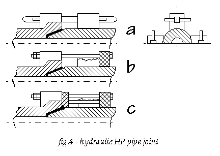
The LP pipe segments are joined with regular bolted flanges, probably fitted with flat gaskets. The HP pipe joints are, as far as could be made out, of the ‘spigot in socket’ type. The mating ends each have four hefty ‘lobes’ with square boltholes in lieu of a continuous flange. Each pair of lobes is drawn together by a square bolt with cotters at both ends. There would be gasket material between the spigot and socket (fig.4a).
One of the lobes on the first segment west of the bypass valve is broken. Repairs were made (at an unknown date) as follows:
- A steel ring about 50 mm thick was fitted behind the lobes on the side where one was broken.
- The four square bolts were replaced by threaded ones with nuts, and the joint was retightened (fig.4b).
- There was probably some leakage, maybe because the original gasket material had been disturbed by motion. To remedy this without dismantling the joint, a second ring, 30 mm thick, was made to fit around the exposed part of the spigot between the lobes; this was then pushed against packing material applied to the face of the socket with threaded bolts supported against the clamp ring (fig.4c).
- Both rings are made up of two sets of half-rings staggered at right angles and screwed together – one more reason to assume that the joint was never dismantled.
This joint exhibited serious leakage during the first attempts at hydrostatic testing (see Sect.3.6 below). As a provisional measure, Loctite and polyester were applied, but if the HP connecting pipe is to be pressurized, more permanent repairs will have to be made.
3.6. Hydrostatic test (water hydraulics operation only)
First attempts at hydrostatic testing revealed the flange leak discussed above, and the new plunger packing showed some leakage as well, which could be reduced – but not completely suppressed – by tightening. A pressure of about 40 bar (550 psi) has been attained. For parts to be subject to pressure, tightness will have to be confirmed at 50-80 bar (700-1100 psi) for water hydraulics operation.
3.7. Filling and draining (water hydraulics operation only)
For provisional filling, a hose will be connected to one of the deaeration cocks on the plunger housings. Eventually a more permanent fill/drain connection with associated valves and piping (to water supply and to outside) will have to be made to a low point of the HP portion of the water hydraulic system.
3.8. Vertical guides and the risk of binding
One respect in which the proposed active hydraulic drive will differ from the original steam drive is, that a single central – albeit distributed – upward force is replaced by two concentrated forces applied symmetrically with respect to the center. This might conceivably cause binding. Vertical guidance is provided by the following :
- Cylinder walls. With the packing removed (see Sect.4.2), there is some lateral play, but in the annular cylinder this is quite small.
- Five piston rod stuffing boxes. These are empty now, but the bronze gland sleeves and the lantern rings allow but little play.
- Two hydraulic ram stuffing boxes.
- Four guide rods for the weight.
- The upward extension of the central piston rod, which runs in a stuffing box situated in one of the structural beams about 5 m above the cylinder cover. (Note that several rods on this engine run in stuffing boxes, not to make a seal, but to provide an adjustable guide)
The various guides are spaced widely apart, both horizontally and vertically, so binding is not expected to become a problem.
Additional note 1996. When the mineral hydraulics system was planned, the risk of binding was looked into again. It was found that skewing would have to be limited to a few mm, and that positive synchronizing of the motion of the weight cap ears will be needed as a further safeguard.
4. Steam cylinder
The space above the pistons is accessible via four manholes in the cover (two for the central cylinder, two for the annular one). These are rather badly aligned with the corresponding openings in the false cover. For convenient removal of the manhole covers, and for easy access (particularly to the HP cylinder) the 1000 kg false cover should be lifted. This turned out to be relatively easy, but replacing it requires accurate positioning. In the early days the false cover would probably be tied to the weight, which was then lifted by steam. Replacing it would require inching down the hydraulic. This is a cumbersome method, considering that even now – with three chain hoists – accurate setting down remains a trial and error procedure. The false cover shows signs of serious damage and repairs, see Sect. 10.9.
The stroke between the stops is about 3 m (10 ft), the top clearance between piston and cylinder cover is appr. 20 cm, one may assume the bottom clearance to be similar, or maybe a bit less.
4.1. Moving the piston up and down
The indoor weight surplus was – acc. to one common interpretation of Simons [4], but see Sect.10.5 and below – assumed to be about 85 tons, producing a gravitational force of abt. 850 kN to drive the pumps. For a first attempt at raising this weight the beam apertures in the windows were cleared (see Sect.7), the outdoor water pumps were inspected and their pistons freed (see Sect.8), one hydraulic ram packing was removed (see Sect.3.1), and most guides were soaked with paraffin and oil.
Eight hydraulic jacks of 200 kN each were installed under the weight ears using a specially designed modular support structure. The maximum upward force of 1600 kN did, at the first attempt, not produce any motion at all. After removal of the piston packing (see Sect.4.2), motion started at 1200 kN. A considerable fraction of this was obviously due to friction and initial sticking. Experiments with alternately lowering and raising the weight a few cm then appeared to indicate a net weight surplus of about 70-80 tons or 700-800 kN.
The piston was eventually raised about 153 cm, that is to slightly above its normal limit.
After several inspection and maintenance/repair activities (including the flame spraying of the plungers reported in Sect.3.2) the piston was lowered to about 90 cm from the lower limit stop. This left enough working clearance above the cylinder cover. Besides, the jacking arrangement will not allow further lowering. Only after the hydraulic cylinders had been fitted early in 1998, the weight could be lowered to its bottom position. Up-and-down experiments now appeared to indicate a net weight force of about 600 kN. In view of what has been noted in Sect.10.6 this was originally thought to be surprisingly low. Re-reading Simons [4], and some further thought and discussions, resulted in the more likely figure of c.600-650 kN for recent times.
4.2. Pistons
In order to keep the center of gravity low, the pistons are designed as hollow bodies, to be loaded with part of the unbalance weight. Simons wrote in [4] – published in 1848, i.e. before Cruquius was ready – that Cruquius and Lynden were to have more piston load than Leeghwater. Cruquius’ supervisor, writing to his superior in 1858 [9], seems so take Simons’ word for it. Probably nobody ever bothered to look. In view of the plans for decreasing the load, it is obviously important to know how much weight is present.
Several piston covers were lifted. Some of the fixing bolts came out in one piece. Many eventually sheared off, badly necked by corrosion. The piston is indeed loaded to capacity; most of the space is filled with (evidently purpose-made) iron blocks of varying sizes, weighing 30 to 70 kg each. Each block has holes for lifting with hammerhead bolts. Grease and water have penetrated the compartments of the annular piston, and fill most of the remaining space. In the central piston (which was much hotter) there is little grease, no water, but a lot of rust. Quantity and removal of this weight are discussed in Sect.6.2.
The contract drawing of the pistons shows two diametrically opposed manholes in the annular piston, providing access to the space below. This location is not very convenient, as these manholes would be hidden under the piston’s top cover, and buried under weight blocks. Both have been uncovered, but repeated attempts at lifting – with up to 20 kN force – failed. Probably the gap between the cover’s bottom rim and the hole is filled with tightly compressed rust. No manhole is indicated in the central piston; maybe access to the space under it is via the equilibrium duct (after removing the valve, of course). These engines were certainly not designed with convenient maintenance in mind.
The total packed piston circumference is about 25 m. With c. 400 mm packing contact height the contact surface area would be about 10 m2. This might well cause sufficient friction or sticking to explain the problems reported in Sect. 4.1, as a very modest contact shear stress of about 0,1 N/mm2 would suffice to generate 1000 kN friction force. It was decided to attempt removal of the packing. This packing is described in [4] as of the usual type, which would be plaited junk (hemp), compressed by a junk ring. The plates in [4] show a section through the pistons for both Leeghwater and Cruquius/Lynden, but the six packing arrangements depicted are all different and some look unlikely (this turned out to be an artist’s interpretation of the contract drawings mentioned in the preface). Pole [10] does not discuss piston packing at length, his plates show just a fairly deep chamber with the bottom sloping down toward the cylinder wall, evidently to be filled with junk only. Later (after considerable progress had been made with packing removal) the following statement was found in [11] : ‘The internal and external packings of the pistons consist of hard cast iron segments at bottom, with gasket above, pressed down by glands, also in segments’. This segmented bottom ring, triangular in shape, 100 mm deep and 25 mm wide, had indeed been found at the bottom of the appr. 415 mm deep and 50 mm wide chamber. K.Brown expressed the opinion [12] that the purpose of these rings was to assist in keeping the piston central in the bore during packing renewal. Correct alignment is important to keep the piston from rubbing against the cylinder wall. Once good alignment has been achieved by carefully positioning the initial narrow coils of hemp behind the segmented ring, the remainder of the task would be easier. Another effect of these segments would be to prevent the packing material from working down into the gap.
Still later, the contract drawing of the piston was found to show the packing chamber of the central HP piston as described above. For the annular piston, however, a second inverted metal ring is shown under a flat junk ring. This would much reduce the wear surface of the packing, which would to a large extent serve as an ‘elastic’ cushion behind the segmented rings. This top ring was obviously removed later (and the junk ring given a sloping underside), perhaps as packing materials evolved.
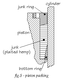
Fig. 5 gives a general idea of the packing arrangement. The chamber is 50 mm wide and about 415 mm deep. The junk ring is held and tightened by nuts on hammerhead bolts (c.265 mm long,1-1/4″ thread) fitted in recesses in the chamber wall. Total piston depth has been measured (by inserting a wire hook down the gap between piston and wall) to be about 665 mm. At the inner circumference of the annular piston there is a 130 mm deep recess so that the piston in its lowest position clears the flange with which the HP/LP separating wall is bolted to the bottom casting. The depth of the piston edge below the packing chamber is thus 120 mm (LP inner) or 250 mm (others). The contract drawings have confirmed this.
The general procedure was to completely remove the junk by ‘digging’ it out with a variety of chisels, crowbars etc., then loosen and lift out the bottom ring, and finally to clear the gap below the chamber by passing a sawblade through it. The following observations were made for the individual packing chambers:
l Outer chamber of annular piston. The junk ring consists of five segments and could be fairly easily removed (both this and the wear on the bolts confirmed, that maintenance was quite frequent here). Much variation in gasket type was found: near the top, square sinnet was most common, with a rubber core in one layer (an experiment ?). Further down, the gasket consisted mostly of flat sinnet, much of it badly worn (on the outside, of course) so that it had been reduced to short strands. Behind the bottom ring little or no wear would occur, but here the junk had deteriorated to a rather amorphous and only vaguely fibrous mass which was tightly compressed, and very difficult to remove. The cast iron bottom ring consists of 7 segments, each 1,5 m long, with joints at an angle. As the total length of this chamber is 11 m, a section of about 0,5 m is not covered. Here the junk had been most difficult to remove. Most of the segments were stuck to the cylinder wall and it took a lot of prying to dislodge them. The piston.cylinder gap below the chamber is narrow; the sawblade could only be passed with difficulty.
l Inner chamber of annular piston. The junk ring is in one piece. Down to the bottom ring all layers were square sinnet in relatively good condition, suggesting that at some time this packing had been replaced in its entirety. An entry in [2] confirmed this: renewed in November 1927. The space behind the bottom ring was filled with a compact mass as described before. The cast iron bottom ring is in 6 segments, and was difficult to dislodge. The gap was again very narrow, and in one place the sawblade could only pass after the piston had been pushed over slightly by driving a wedge in the packing chamber.
l Chamber of central piston. The one-piece junk ring was broken, and had been repaired with iron strips bolted to the top. The gasket type varied, more or less as in the outermost chamber, and much of it was difficult to remove. Surprisingly, the two layers behind the bottom ring were in fairly good condition; the narrow bottom layer consisted of twisted rope instead of plaited sinnet. A few pieces of flat sinnet, obviously saturated with graphited grease, were solidified to a hard and brittle mass. This packing was, of course, exposed to fresh boiler steam. This may also have been a reason to make the bottom ring of bronze, and to fit it quite accurately. There is no appreciable gap between the four segments. It is not known whether this bronze ring is original. The gap below the chamber is about 7-10 mm wide. A sawblade was passed all around all the same, to make certain the gap is open.
Bootsgezel writes in [13] : The engine could work seven full days with one set of packings. In years past a kind of spun yarn packing boiled in tallow with black lead was used of rectangular cross section of 80×80 mm , but he gives no source for this statement. The size appears on the large side, and the many different layers found would seem to indicate a practice of just adding a layer or two when the junk ring could not be tightened further, and to (wholly or in part) renew only if unavoidable. A seven day period seems more likely as a tightening interval than as the total life of a set of packings. Findings of Middelkoop [14] and repair notes [2] confirm that packing maintenance was a major activity.
4.3. Piston rods
The wrought iron rods are quite badly corroded in places, particularly the portion which is in the stuffing box when the engine is parked. Extensive and costly repairs would be needed for smooth and tight running, which adds to the problems of steaming. The relative ease with which the annular piston could be pushed over (slightly) by wedges has already been mentioned. While replacing the gland of the central piston slight lateral movement was also observed. As the weight-plus-piston-rods structure is quite rigid, this may indicate slight play of the rods in their stuffing boxes.
The stuffing boxes have been emptied and cleaned. Most of the packing consisted of plaited hemp (square sinnet), but rubber cores and lead fabric wrapping was also found. The bronze sleeves of the box and gland, and the bronze lantern ring, ensure reasonable guidance. At the position of the lantern rings the stuffing box walls were heavily corroded, in places to a depth of 1 cm or more.
5. Miscellaneous parts
l The two air pumps have double-beat cast iron discharge valves at the top, which constitute the bottoms of two hot wells. The valve seats are formed by rings of woodblocks. The hot wells have overflow ducts to a common collecting ‘box’ which in turn discharges to the collar launder outside. This ‘box’ is of iron plate riveted to angles. Much of the original construction is heavily corroded (the top is completely gone), and repairs had been effected by lining the box with brick. After 1933 the discharge duct provided convenient entry and shelter for pigeons, until the box was filled with builders’ rubbish; this has now been removed. In the side wall of each hot well are four one-inch holes, slightly below the overflow duct level, and now plugged with wood. If open, these holes would have returned some of the hot condensate to the cistern (heating it up), with the duct serving as a secondary overflow. The reasons for making (or plugging !) these holes are not known.
The bronze piston rods are in excellent condition; their stuffing boxes in the hot well bottom have been emptied. The rods and pistons are quite free to move.
The buckets are really bucket-shaped, quite deep, with a bronze double beat valve similar in shape to the discharge valve, and a packing chamber with a junk ring at the rim. Tightening is quite difficult (lift the discharge valve, and reach through the valve opening). For replacing the packing the entire hot well would probably have to be removed. The hot well fixing bolts were submerged, and are stuck and badly corroded. Still, [2] reports frequent renewal of (or adding to) these packings, as late as December 1928. The reasons for the deep bucket shape are not known, nor are those for making some of the submerged parts of bronze/brass and others of iron.
Both air pumps have been overhauled (dismantled, cleaned, Molykote lubricated, assembled) to ensure smooth motion without pumping function This means that e.g. the wooden valve seatings were left as they were.
l The hot well pump pumps water (condensate plus injection water) from the east hot well to a feedwater cistern in the boilerhouse. Probably this pump was not part of the original design; in the early years the engineer experimented with various arrangements to keep the condenser cold, to recycle (or not) the condensate, etc. The present pump is driven from beam #3. It draws from the east hot well via perforations just below the overflow duct level; the top row of perforations has been plugged with wood.The effect of this would be that the remaining perforations are always below the hot well level. This cannot have been done to prevent the drawing of air, as the pump inlet is further down; maybe it would prevent dirt floating in the hot well from entering and fouling the pump. The plunger has a wrought iron core to which a cast iron sleeve has been fitted with a nut at the bottom and a cotter at the top. The pump body has a long vertical crack (water hammer or valve blocking ?), jury-repaired with clamps, angle irons and packing material. The condensate pump’s stuffing box has been emptied. All bearings and guides have been overhauled and long-term lubricated.
l The condenser cistern has been inspected, although its condition is of no immediate importance to the moving of the engine. The cistern is constructed of cast iron plates bolted together. The two air pump barrels are supported by brackets cast integral with these plates. The bottom ends of these barrels are connected to the condenser barrel through ducts, each with a rectangular cleaning cover at the top, which provides access to the condenser foot valves. The injection water is admitted from the cistern to the condenser jet by a system of three valves :
- a regulating valve, set manually from the driver’s stand by a lever with locking pin; the supply to this valve is via :
- a main double-beat inlet valve about 70 cm below the cistern’s water level, coupled to the exhaust valve, and providing the main injection supply;
- a small auxiliary inlet valve at the same height, adjusted by the same lever as the regulating valve via a slotted link, providing a small but continuous injection supply at high settings of the lever.
There is a thick layer of rust, dust and rubbish on the bottom but it appears that, if necessary, the cistern could be restored to function. Cleaning has been started (March 2001) as a non-urgent activity.
l The end stops for emergencies work on the ears of the weight cap. These ears slide on the guide rods, and they also carry the rams of the hydraulic (see Sect.3) and the air pump beams (earlier in this chapter). The bottom stops are contained in the pedestals (see Sect.2.3). When it was decided in 1995 to look into the feasibility of locating the add-on hydraulic cylinders here, the buffers were removed. A 19th century sketch indicated a horizontal partition at about half-height, with some sort of buffer elements stacked on. The first guess was, that these might consist of felt and/or leather, as rubber buffers were unknown at the time. As it turned out, the partition did not exist, and the buffer consisted of blocks of wood stacked on the cast iron bottom. There was some leather or hide interposed, but too little to add appreciably to the very limited buffering action of the wood.
The top stops, keyed to the guide rods, have not been touched, they would appear to be of similar (but much lighter) construction.
The pedestals have been emptied, and a large hole has been made in the cast iron bottom (and a supporting wrought iron plate under it) to accommodate a hydraulic cylinder.
l The park props supported the weight/crosshead in the half-stroke position during long idle periods. They were 1,5 m long oak timbers, 20 x 30 cm with iron bands at the ends. The original props were inspected and judged unreliable (some woodworm). They are also unwieldy (80 kg) so, with the possible need for more frequent handling, a lighter alternative was sought. The load per prop would be about half the indoor overweight or about 320 kN (or less, as some weight observations seem to indicate), assume conservatively about 500 kN.
Mild steel pipe c.200×4,5 mm would weigh in at 33 kg, high-strength steel c.200×2,5 mm would be 18 kg, aluminium c.200×4,5 mm is 12 kg. For buckling, the lower specific weight of aluminium would be more than offset by its also much lower modulus of elasticity – but buckling is not the determining factor, as the following summary shows.
Data: length l =1500 mm, diameter D =200 mm, compressive load F =500 000 N
- Strength in compression: yield strength c.240 N/mm2, design stress two-thirds, is f =180 N/mm2, minimum wall thickness d =F / (pDf)=4,4 mm.
- Rod buckling: both ends simply supported, E =70000 N/mm2, required margin 3, minimum wall thickness d =(24Fl3)/(p3D3E)=1,5 mm.
- Shell buckling: (Roark 5th ed.,table 35, case 15) minimum wall thickness 2,5 mm.
Aluminium pipes with welded end plates have been installed. For still more handling convenience, handles might be clamped on (no welding !!) in a suitable location. If desired, a mockup wood casing might be made, adding about 10 kg to the weight.
Note: the decision to put the add-on hydraulic cylinders inside the pedestals necessitates a new solution for parking support. The props described had to be discarded. Following are the calculations for an alternative.
Consider two props, each consisting of two aluminium channels 160x80x10 mm clamped around one of two diagonally opposed guide rods (to center the support). Weight c.12 kg per channel.
Data: length l =1500 mm, diameter D =200 mm, compressive load F =500 000 N, assume that (due to uneven support surface) load is taken by a single channel.
- Strength in compression: single channel cross-sectional area A = 3000 mm2, yield strength c.240 N/mm2, design stress two-thirds or =180 N/mm2, stress 500/3 = 167 N/mm2, which is acceptable.
- Rod buckling: both ends simply supported, E =70000 N/mm2, required margin 3, minimum second moment of area I = 1800000 mm4, margin 1,7. This is much less than the normally required value, but the assumptions about nonsymmetric weight distribution among and within props (putting 80 % or more of the total overweight on a single channel) are very conservative. To be totally on the safe side, three sets of (removable) couplings between the two channels have been fitted.
6. Weight
6.1 General discussion
The central weight or ‘great cap’ now consists of a hollow cylindrical open-top main section with two ‘ears’ clamped and bolted on Originally the ears were cast integrally, what we see now is a repair (see Sect 10.9). These ears slide on vertical guide rods, and outer projections carry the hydraulic rams (see Sect.1 and Sect.3.1). The central section is divided into six compartments which can be loaded with purpose-made cast iron weights, clamped to prevent rattling etc. In four of these compartments, openings are left for the beam connecting rods which extend down to bearing blocks fitted to the underside of the weight and covered by two conspicuous copper pans which provided oil-bath lubrication. The remaining two compartments have loose plate covers. In later times scrap etc. has been added to the weight in all compartments.
An indoor weight surplus is essential for the operation of this type of single acting nonrotative engine, and remains so for hydraulic drive. This surplus must be sufficient to overcome friction etc. and – should it be decided to operate one or more of the outdoor water pumps – to provide the required lift.
The net lifting force needed for one pump is about 120 kN (see Sect.10.5). Should it be desired to restore one pair of pumps to operation, then the required force will be 250-350 kN, to be provided entirely by the weight.
The total unbalance force of the engine (when still working) is not known accurately, but has been estimated at 600-650 kN (see Sect.4.2). A reduction (by removing weight) of 250-350 kN is thus desirable. This will change the total equivalent moving mass of roughly 250 tons by only a few per cent.
The relatively large reduction of the unbalance force plus the relatively small change in moving mass will result in more sluggish dynamic behaviour but, as the stroke rate will be reduced, this does not seem objectionable.
6.2 Weight removal
In the course of 1990, 8440 kg weight was removed from the weight cap which is now empty. Another 13555 kg was then removed from the pistons. This is a much slower, more arduous and messier job, completed early 1997. In the annular piston (7985 kg) the blocks are embedded in a goo of old, half-decomposed grease and water, from which they can fairly easily be extracted. The blocks in the central piston (5570 kg) are ‘cemented’ in tightly compressed rust, and removing a block appeared only possible if the rust could be removed first. Various methods were tried in the early 1990s, from drilling and grinding to a hot mixture of strong acids (Blekkenhorst), all to no avail. In 1996 Harry Kruk devised a brute-force method using the more powerful tools then at our disposal, which proved effective. If we allow c.200 kg for grease, water etc., the grand total of removed weight is c.22.2 t, leaving c.40 t (400 kN) structural indoor overweight.
6.3 Bearing overhaul
The connecting rods and their bearings for the connection rods were dismantled and all bearings cleaned, overhauled and refitted with longlife grease. The bottom bearings, having been immersed in an oil bath and oscillating only slightly, were in excellent condition, covered in a layer of hardened oil which could be chipped off.
7. Beams
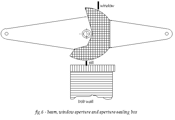
There are eight main beams or “bobs”, one of which had been disconnected, but has since been reconnected (see Sect.10.5). The beams are of cast iron flanged latticed ‘hollowwork’ design, 2 x 5 m (equal beam). The trunnion bearings rest on cast iron soleplates. Their centres are about 60 cm inside the windows, so the top and bottom gaps between beam flanges and window aperture vary during the stroke. In addition, there are substantial side gaps between the beam flanges. This was probably found objectionable (draught, birds), and wooden boxes were fitted to the beams to obtain a constant narrow gap as shown diagrammatically in fig. 6. Such a box is also found on the single disconnected beam, so these boxes were probably fitted early on, maybe already in the building stage. They are not shown in contemporary illustrations, however. Such boxes, of varying design for different beam types, were not uncommon in Cornwall. Occasionally, one finds plain boards, which seal the aperture in a single (parking) position only.
The outdoor portions of these boxes (which would have been the worse for exposure anyway) were cut off after 1933, and the gaps were sealed with slats. These have now been sawn through from the inside with a compass saw, re-establishing a gap.
For regular motion over the full stroke more permanent provisions are rquired – in 1996 work started on replacement boxes in red cedar wood (structure similar to pine, but much more durable). By summer 2002, six boxes were complete, with work on the remaining two progressing well.
The air pumps are driven by two additional (half-)beams. These are also of lattice design, but one has a solid central portion. This one was renewed in 1851 (see Sect.10.9).
All indoor and outdoor beam end bearings have been dismantled, repaired, long-term lubricated and re-assembled. The outdoor (nose) bearings have been fitted with grease nipples. All beam trunnion bearings have been cleaned and long-term greased.
8. Outdoor pumps
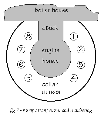
The plan sketch fig.7 shows the arrangement of the pumps and the numbering convention of [2], which has been adopted for this report.
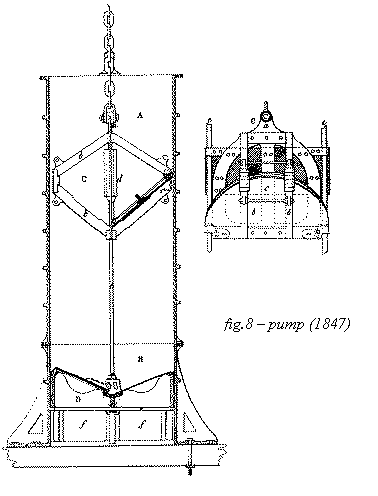
Fig.8 shows the 1847 drawing of one Cruquius pump from [11]; this differs slightly from the oldest known drawing (1846), and also from today’s situation, after a replacement and numerous repairs.
Each pump barrel is flange-mounted onto a c.1,5 m tall lantern piece B. This lantern piece has six openings f (hence the name) which admit water to the pump’s foot valve. It also has six external feet, which are bolted to the timber floor or to the grating beams (see Sect.2.1). As the lantern piece is thus firmly affixed to the pile foundation structure, it can to a limited but sufficient degree absorb upward forces (friction, valve dynamics, etc.). The piston or bucket C is an open frame built up of cast iron and wrought iron pieces, including extra weight d to speed up the descent of the bucket. The assembly was originally guided by two rods e and by four gunmetal facings on the knee-pieces b. The bottom ends of the guide rods were used to bolt the foot valve frame and hinge supports to the seat in the lantern piece, their top ends are affixed to brackets bolted to the pump flange. Where the cast-in boltholes in that flange would not properly line up, extra holes were drilled – these can still be seen on some pumps. The piston was suspended from the beam end by a rod and a length of patent chain. At an unknown date later in the 19th century, the pistons – probably the worse for wear and tear – were replaced with a design which is only slightly different. They were now suspended from a plate link chain, which would prevent turning of the piston to a sufficient degree, obviating the need for the guide rods, which were removed. The new chains enforced a specific piston orientation, i.e. piston valve hinge line in plane of beam, that is “radial”. As a consequence, the foot valve hinge line would also have to be radial. This meant that in many (maybe all) pumps the original foot valve fixing brackets could no longer be used. In pumps 2 and 6 – and probably in most other pumps – the foot valve frames are now clamped to their seating flange in the lantern piece by a cast-iron crossbar underneath. Where the old pistons had (four) guide rod sleeves, the new ones were fitted wih additional gunmetal blocks, bringing the total number per piston to eight. Two large semicircular plate iron clacks c complete the bucket. These are fitted with pine rims to minimize the gap between piston and barrel, and with a strip of leather on top of this, to make them tight. The wooden rims and leathers are held in place with bolted-on plate iron glands which also provide extra weight to aid valve closure. An earlier drawing shows extra weight blocks on the clacks, but by 1847 these were gone; maybe the clack plate thickness was increased instead.
The foot valve D is a simpler casting, again with two semicircular clacks, sealing on rims of beechwood blocks with lignum vitae bottom wedges, rammed into grooves (fig.9).
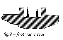
All pumps have been inspected. Pump 7 was disconnected (see Sect.10.5). There is evidence of many repairs to the barrels, the frames and the clacks. The bores of several pump barrels show areas with chisel dressing marks, mostly near the top flange. This may be the result of removing casting flaws, and indicates that the pump barrels were never bored or otherwise machined. The bucket chains are of varying length, probably adjusted individually so that the leather strip will clear these rather rough dressed areas. A wear “step” in each barrel – discernible in skimming light – marks the top position of the bucket. Pump rod 5 has a socket-and-cotter repair at the top.
Initially, all bucket clacks were opened a few cm and secured in that position. For pumps 1, 3, 4, 5, 6 and 8 the buckets have been found to be quite free to move. For pump 2 this was not ascertained initially due to lack of time. In keeping with Murphy’s law, this one turned out later to be firmly stuck (and very difficult to free) during the raising of the weight (see Sect.4.1). One of the wedges used for prying open the clacks, had inadvertently been left in place, resulting in some problems and in erroneous weight readings when the indoor weight was lowered.
At the start of the hydraulic project c.1995 it was decided to operate two diametrically opposed pumps (Nrs.2 and 6), and to have the other pumps run idle with open bucket valves. The final decision whether or not to reconnect pump 7 was postponed, but as some of the other pump connections had to be disassembled anyway, one set of parts was copied to be available for pump 7. The pump was eventually reconnected (see Sect.10.5).
For the two operating pumps, an attempt was made to lift the foot valves out, for cleanup and repair, as used to be done quite regularly during Cruquius’ operating life. For pump 6 this worked (with difficulty); the valve frame showed substantial repairs. The remains of the old valve seal were removed from the grooves, and new blocks (crosscut beech, with lignum vitae bottom wedges) inserted.
Foot valve No.2 turned out to be more stubborn. Its frame is sitting askew, with all nooks and crannies at the circumference filled solid with (expanded) rust, or with tar, red lead, dirt etc. All attempts at moving this frame failed. Cleaning and repair had to be done in situ, in rather cramped conditions.
The sealing surfaces (both clack surface and wood blocks) were carefully dressed. Unexpectedly, the seal turned out to be less than perfect, may be due to the somewhat unfavourable slotted hinge arrangement. Improvements to this (suggested by an early drawing!) would be fairly easy for pump 6, but well-nigh impossible for pump 2.
For all pumps the heavily rusted bucket chains were dismantled and the buckets lifted out for cleaning. Extensive cleaning and repairs – mainly for buckets 2 and 6 – have been effected by an outside firm (Messrs.Blom). Particular attention was needed for the gunmetal guides, some of which were badly worn or missing. Replacements are volunteer-made.
The wood rims on the clacks were replaced in Russian larch. The flexible seal presented some problems. The remains of the old leather strips were diagnosed by an expert to be heavy-quality (4-5 mm) cowhide. Upon his advice the same leather was used on pump No.6, soaked in water to soften before shaping in place, and then treated with oil (ordinary mineral engine oil). Pump No.2 was experimentally fitted with 3 mm polyurethane (Vulkollan) strips. Neither was a success. The leather swelled, became very soft, and in places it worked into the narrow gap between wood rim and barrel. The Vulkollan did not swell, but due to its flexibility it also worked into the gap. After a few weeks both were replaced by a heavier (5 mm) Vulkollan which performs reasonably well.
The piston clack seals have inherent weaknesses: The semicircular circumference of each clack has two cutouts for the vertical frame members carrying the guide shoes, and the seal has to negotiate these. At the clack hinges special seal flaps have to be provided. All this produces corners which inevitably leak.
If two pumps are to operate, these will need an unimpeded water supply. Inspection revealed, that the foundation floor is covered with a thick (1 – 1,4 m) layer of rather dense mud, mixed with tree branches, decayed timbers, and other rubbish, effectively blocking any flow to the foot valves. Complete removal of this layer is not feasible (it would entail extensive dredging in the supply channel). It was decided to build two segmented cylindrical steel shells to stand on the foundation floor around pumps 2 and 6, allowing cleaning inside. Holes are provided in these shells, at suitable locations to admit water, but preventing both floating and sunken rubbish to enter the lantern pieces. The shells have sacrificial-anode cathodic protection. Assembling and erecting these shells, from a wobbly working raft, turned out to be a major task. As they would have to be pumped out, at least partially, for cleaning and foot valve work, it was essential that leakage at the bottom end should be limited. The grating beam ridges (see Sect.2.1) would be a problem here. This was overcome by laying down (using a pipe funnel) a ridge of concrete along the bottom edge.
Priming of the pumps can no longer be done in the old way (see Sect.2.4). Due to the considerable leakage, however, substantial priming facilities are required. After a number of experiments (mostly failing through insufficient capacity), Piet van Putten designed and made two siphons of 125 and 160 mm dia., with valves for starting (with a small priming pump) and stopping (vacuum breaker). These turn out to be just adequate as a bootstrap for the initial two or three pump strokes, which then complete the filling of the barrel.
Why cannot a suitable connection to the canal outside be made for this purpose ? That would be a closer approximation to the old method. This would require a substantial pipe from the canal, through the dike, to the collar launder. Preliminary calculations indicate a required diameter of 300-350 mm. There would be polder safety implications. Also, the level in the collar launder cannot be allowed to rise to the canal level: the renewed collar launder floor is not strong enough (see Sect.2.4), and the museum lobby would be flooded. Still, the idea has its attractions, and may be further investigated later.
9. Valve gear
Note on terminology: The three valves of a Cornish engine are controlled via rods/links from three arbors at the driver’s position. Each arbor has a handle for manually closing the valve against the action of a weight; it is held shut by a kind of pawl called a scoggan, with a release lever or scoggan catch. The usual arrangement is, that the lower arbor controls the exhaust, the middle one the equilibrium and the upper one the steam valve. Correspondingly, the exhaust handle is called the bottom handle. However, for the equilibrium handle in the middle, the name top handle is often used, reminiscent of the Watt era when engines had only two arbors. The steam handle at the top is called the steam horn. This is often duplicated for reliability reasons (see also Sect.10.9). During automatic operation the valves are closed by clamps or slides on the plug rod, which strike the handles. The steam slide is usually adjustable and quite long (to allow overtravel after cutoff).
According to contemporary writings (e.g. [4]) HP cutoff was originally at approx. 50%, as would be normal for a compound Cornish engine. The present arrangement of the steam slide only allows much later cutoff, in the 80-90% range (see discussion in Sect.10.5). To achieve this late setting the steam slide fittings were evidently moved up on the plug rod. Marks on the rod still betray the original position.
Steam horns are always shaped to allow overtravel of the slide after the closing of the steam valve. In this engine this is achieved by using very short (dual) horns, which makes manually closing the steam valve quite difficult.
When the weight was raised (see Sect.4.1) it was noticed that, at the setting as found, the steam slides touch the horns at about 70 % and that at 100 % the scoggan catch engages the scoggan, but the horns are still partly ‘under’ the slides. At 100 % the valve must obviously be shut, so obviously the links (and possibly the scoggan) have been adjusted to achieve this with the horns not fully ‘home’. As a result, any overstroking will result in compression of the steam valve links. This may have caused the slight buckling which was evident in the vertical steam valve link.
The equilibrium scoggan has also been turned slightly on its arbor and rekeyed. The effect would be, that for most of the steam stroke the equilibrium valve is held shut by the exhaust quadrant rather than by its own scoggan (which takes over only when the exhaust is fully shut). At the end of the pump stroke the equilibrium handle must be pressed fully home (well beyond the scoggan engagement point) to allow the exhaust to open for the next stroke. The purpose of this arrangement (which increases wear of the quadrants) is unclear. The equilibrium scoggan has been returned to its ‘original’ position and rekeyed.
The clamps are wood with brass sideplates and leather-covered wear surfaces. The leather on the steam slide extends only a short way up and the tensioning device has been removed, as for the very late setting this was all that was needed. When the leather wears thin, one sideplate of each steam slide touches the handle of the corresponding horn; the wear on handles and slides shows this to have been quite common.
The valve gear has some features not often found in Cornish engines.
- The steam and exhaust arbors are interlocked to positively prevent the steam valve from opening before the exhaust valve does. This sequence is normal driving practice, but it is rarely enforced by an interlock.
- A rod and lever arrangement, operated by the exhaust arbor, blocks the equilibrium cataract until the exhaust valve is shut. This should improve the stability of the rather brief equilibrium release delay.
The valve gear has been cleaned and lubricated, and now moves without difficulty. The brass bearing caps have deep recesses, mostly filled with grease-storing materials such as leather, cardboard. The rather loose bearing setting desired, with nuts no more than hand-tight, increases the risk of parts disappearing. For this reason, distance washers have been fitted which allow the nuts to be fully tightened. Maybe eventually some adjusting of weights will be desirable (e.g. the exhaust valve opening weight, which seems excessive in the absence of a pressure differential), but this may be postponed. For the simplest forms of motion, if the valve gear has no function, the valves should be secured in their closed position. The original rod-plus-ring for securing the bottom handle is still present. For the top handle (usually left free in Cornish practice) the original chain-plus-ring (visible in [5] fig.355) is gone, a replacement has been fitted – in fact, this had been ‘re-invented’ before the original had been noted in the photograph !
Returning the steam slide fittings to their original position might be considered.
Somewhat surprisingly, the steam valve stem – which had moved before – became stuck during the first raising of the weight (see Sect.4.1); this was only noticed after considerable distortion of the vertical link had already occurred, adding to the slight buckling mentioned earlier. The link has been straightened.
The cataracts are not essential for hydraulic operation as such; they may however aid in making motion and control more realistic. They have been overhauled, on the main cataract the plunger had to be replaced. Originally, the cataracts ran on water. They have now been filled with light oil which makes no difference functionally, but which prevents corrosion.
10. Working life : operational aspects
The following observations have no direct bearing on the intended operation using hydraulic power. They are included here, as they may lead to a better understanding of some operational aspects of the engine’s history.
10.1. Principal engine data
HP piston diameter 2146 mm (84″)
LP (annular) piston dia. 2235 mm (88″) inside, 3664 mm (144″) outside.
stroke 3048 mm (120″) between limit stops.
top clearance 200 mm (8″) if at limit stop [approx.]
bottom clearance unknown
HP piston rod diameter 305 mm (12″)
LP piston rods (4) dia. 114 mm (4.5″)
ratio LP/HP piston area 2.84
stroke rate 10 per minute rated, but usually 5-6 per minute.
power c.220 kW (300 hp), later up to 350 kW (500 hp).
boilers:
1849 six Cornish, rated at 2.4 bar (34 psi), heated surface initially abt. 55 m2 (600 sq.ft) each.
c.1855 four flametubes behind firetube replaced by single tube, heated surface reduced to 45 m2 (480 sq.ft).
1860 four similar boilers added; pressure rating in following years raised to 3,6 bar (50 psi).
1888 replaced by six Lancashire, rated at 4,5 bar (65 psi), heated surface 66 m2 (1060 sq.ft).
eight outdoor water pumps (mostly seven in use):
barrel diameter 1854 mm (73″).
stroke 3048 mm (120″).
lift 4,5-5 m (180-200″) average.
delivery rate 250 m3/min (55000 gals/min) with 7 pumps,
at 5 strokes/minute, with spillage estimated (optimistically) at 10%.
10.2. Design capacity
The required drainage capacity had originally been specified on the following basis:
- After initial drainage two pumping stations would have to discharge the maximum net monthly influx (rain+percolation-evaporation) within one month. This worst-case assumption accepted wet-land periods of up to a few weeks, and would on the other hand result in the pumping stations being idle for part of the year.
- To have two pumping stations reliably available, three were to be built.
- For initial drainage, continuous operation of (if possible) all three was envisaged for a period of about 19 months.
- The inherent efficiency of the Cornish engine would be used to best advantage if, as the lake level fell, capacity would be traded for lift by progressively disconnecting pumps (see Sect.10.5 for details).
10.3. Efficiency or duty
The traditional measure of efficiency of the nonrotative pumping engine is the “duty” expressed as the quantity of water (in pounds) raised one foot at the expense of one bushel (94 pounds) of “best Welsh steam coal”. A duty of ten million corresponds to an overall efficiency of about 1 %, or a coal consumption of about 8,5 kg per hp·hour.
In the design contract for the Haarlemmermeer engines, the consulting engineers Gibbs and Dean undertook to design an engine delivering 350 hp at 10 strokes/minute at full lift of 5 m with a duty of at least 70 million (i.e. 7 % overall efficiency). This would correspond to a coal consumption of roughly 600 kg per hour.
[4] reports the results of trials conducted in 1846 with the Leeghwater engine, which had eleven pumps with the same total piston area as Cruquius’ eight. During the trials only nine pumps were connected, and a small portion of the lake was temporarily endiked, forming a “mini-polder”, which allowed varying the lift. The trials started with 2,7 m lift, and at 4,1 strokes/min an efficiency of 2,4 % was obtained. For increased lift the efficiency rose to a maximum of 7,1 % for 4,6 m lift and at 5,8 strokes/min (278 hp). When after this result the speed was raised to 6,4 strokes/min, power rose to 312 hp, but efficiency dropped sharply to 4,3 %. The highest speed reported is 7,5 strokes/min. No details of steam pressure, weight, cutoff etc. have been found to date, so it is not known if these were optimized for every value of the lift.
These results appear to indicate that the specifications were not fully met, and that pronounced optimum efficiency conditions exist. Many of the changes etc. discussed below would imply a substantial reduction of efficiency. It is difficult to find hard figures, and operating conditions probably varied over the years. P.Boekel ([18], particularly pp202-218) lists figures mainly for the early 1860s. These are far from comprehensive, and now quite difficult to interpret: maybe even then his source material had gaps, and he was no engineer. He recognizes the variability ”each year is different, and hard-and-fast calculations cannot be made”. From his data, a ball-park figure of 1000 kg/h may be estimated; this would be in fair agreement with the efficiency figure of c.4,5% he implies elsewhere. Not bad, considering all the adverse changes.
10.4. Stroke length control
An important operating problem with non-rotative pumping engines is stroke length control. Overstroking can result in serious damage. Understroking, while not immediately damaging, degrades performance and may stop the engine if not corrected by the driver. The two halves of the stroke (designated here as steam stroke and pump stroke) each require their own provisions for control, adjustment and safety.
l The steam stroke starts when the exhaust and steam valves open as their scoggans are released. Steam enters the cylinder, its flow rate usually controlled by a throttle valve – the steam governor. At some point during the steam stroke the steam supply is cut off, and during the remainder of the stroke the steam expands. Gravity and falling pressure slow down the piston, and bring it to a stop. Near the end of the stroke the exhaust valve closes. The volume of steam in the exhaust side clearance space is trapped, but this cannot do much cushioning, because of the low initial pressure (i.e. an imperfect vacuum).
The most important means of steam stroke length control are steam throttling (easy and flexible, but bad for efficiency or ‘duty’) and cutoff adjustment (maintains or improves duty, but is rather sensitive and requires more driver skill). Some of the highest-duty Cornish engines were built without a steam governor; but often a throttling device was fitted later, sacrificing duty for convenience. Cutoff might range from 10-15 % to nearly 100 %, but 20-50 % would be common. In some cases extreme throttling (“wire drawing”) was practised. This is now known to be wasteful, but at the time thermodynamics was still in its infancy, and even experienced men like William Husband of Harvey’s (who supervised the building of Cruquius) seem to have harboured the notion that throttling was of similar benefit as expansion, as either reduces the pressure in the cylinder [15].
l The pump stroke starts with the release of the coupled equilibrium and hydraulic bypass valves. When these close near the end of the stroke, the water in the hydraulic is trapped again, and this appears to be the principal agent to stop the engine – fairly abruptly. Speed and stroke length control is mainly by adjustment of the surplus of dead weight over pump load, i.e. by adjusting the weight. This conserves duty, and in a traditional Cornish engine with a constant (or only very gradually varying) pump load this adjustment is fairly convenient. When, however, more flexible short term control is desired, equilibrium throttling may be resorted to at the expense of duty.
On traditional Cornish engines equilibrium pipe throttling is rarely found. The Maudslay and 100″ engines at Kew Bridge are among the few known examples. The Haarlemmermeer engines all had equilibrium throttling provisions (possibly to avoid having to adjust the weight for lift fluctuations or when – not infrequently – one or more pumps would have to be disconnected for repairs [14]). In Cruquius and Lynden additional control was possible using a throttle valve in the hydraulic bypass connection – this appears, however, to have been seldom if ever used.
10.5. Adjusting to varying load
The Cornish engine works most conveniently and efficiently with a constant load, implying constant work per stroke. Power is then easily varied by changing the stroke rate – i.e. adjusting the pauses of the cataracts.
For an existing polder the lift (being the level difference between polder and reservoir) varies only slightly, and so an engine can be designed to suit this maintenance drainage task very well. During initial drainage, however, the lift (and thus the load) increases gradually from zero to its final value.
Load variations may be accommodated in a variety of ways.
- Adjust both the weight and the boiler pressure. This tends to maintain efficiency, but weight changes are not easily or quickly made, and the trouble would mainly be taken for large and/or long term load changes. There is an obvious maximum, dictated by the boiler pressure (depending on the cutoff as well, see below). If some of the unbalance weight is fixed or structural, this sets a minimum.
- Adjust cutoff. Later cutoff increases work per stroke, but reduces efficiency. The adjustment is quite sensitive, as already noted in Sect.10.4, and so it is not very convenient. For late cutoff a given boiler pressure can drive a full stroke for a larger weight, thus stretching the range of weight at the expense of efficiency.
- Adjust equilibrium pipe throttle. This throttling “siphons off” some of the potential energy of the weight and converts it into useless frictional heat. It is wasteful, but convenient, and suitable for small short term variations.
In Cruquius the structural fixed indoor overweight with empty pistons and weight trough is about 40 tons, exerting about 400 kN. For h m lift one pump of 2,7 m2 piston area exerts 27h kN. Added to this would be friction, according to [16] amounting to about 20 kN per pump. The structural weight would then be sufficient to drive eight pumps at a lift of about 1 m, discounting LP piston work (which would increase the figure).
Various sources quote different steam pressures for the initial years, and it is not always clear if absolute pressure or gauge pressure (= overpressure = one bar less than absolute pressure) is meant. The earliest and most direct sources are the Stoomwezen government inspection records, and Simons [4]. The Stoomwezen records quote the test pressure rather than the rated operating pressure, but the law links the two – implying a boiler rating of 2,4 bar gauge in 1856 (start of records). Simons quotes 3 bar absolute, i.e. 2 bar gauge – implying that he observed a margin relative to the rating. The rated pressure of 2,4 bar working on a piston area 3,6 m2 could lift about 860 kN, i.e. statically raise a weight of about 86 t if no vacuum present (startup conditions). The weight can be raised full stroke if no cutoff applied. Acceleration of about 250 tons of machinery (crude estimate), and friction, would be extra, so a practical limit to the weight would be lower, maybe c.65 tons.
Note that the 86 t calculated above, appears strongly reminiscent of the 85-86 t mentioned by Simons on p.8 of [4]; the significance of the two figures is, however, fundamentally different: above is computed the maximum weight that can be raised with the rated boiler pressure under starting conditions (no vacuum). Simons gives (with little underpinning) the weight required under operating conditions with compound action, full vacuum, and all pumps working at full lift. That the two figures are equal, would appear to be a coincidence.
For the first quarter of the initial drainage, therefore, Cruquius could operate with eight pumps, and with empty weight trough and pistons. For the first few months even this minimum structural overweight was excessive, and in addition to pump stroke throttling (in the equilibrium pipe and also in the hydraulic bypass, see Sect.3.3), wooden boxes with weight blocks were hung from the outdoor beam ends. HP cutoff might initially have been 40-50%, later possibly 70% or more (see also Sect.9)
From lift abt. 1 m, the pistons and weight trough could be filled and drainage could proceed to take the lake down about 2 m, With six pumps c.65 ton weight would work up to c.3 m lift, and with four pumps the full lift of c.5 m could be mastered. All this is without the supplementary power of the annular LP piston – which is not available during starting. After the engine has been started and is working regularly, that additional power will enable the driver to use earlier cutoff, or (wasteful, but convenient) to apply more steam throttling.
This procedure of trading capacity for lift during initial drainage was planned (see e.g. § 359/360 of [17]) to maximize efficiency, and capacity would thus being reduced (over the initial drainage period) from nearly 1 million m3/day to some 0,5 million m3/day per pumping station at the rated 10 strokes/min. For the more practical 7 strokes/min average, final capacity for three continuously working pumping stations would come to roughly 1,5 million m3/day. The volume to be pumped out during initial drainage was about 800 million m3, thus requiring about 1,5 years, with some allowance for maintenance etc. Various setbacks (mostly non-technical), pushed this up to over three years.
After initial drainage the volume to be pumped out annually would be about 55 million m3, but rainfall is distributed very irregularly, so [17] §311 puts the maximum monthly discharge requirement conservatively at 36 million m3. At optimum efficiency (and number of pumps halved) two pumping stations could just make this. This would have ensured discharge of the maximum one-month influx within a month – the design requirement – even with one pumping station out of order.
Soon this was considered to be inadequate – perhaps already before the initial drainage had been completed. Evolving agricultural practices (such as mechanization) demanded tighter water table control, i.e. higher instantaneous discharge capacity. These requirements could be met by the three pumping stations if more pumps could be connected at full lift. This would mean adding more weight, pushing the boilers to their pressure limit, and using (much) later cutoff – all playing havoc with efficiency, but this was either not understood, or maybe simply accepted (as being cheaper than adding another pumping station). It seems likely, that the starting aspects discussed in Sect.10.6 , together with boiler pressure limitations, eventually limited the number of pumps to seven, thus accounting for Cruquius’ permanently disconnected pump. For a long time we thought, that the choice of the disconnected pump (No.7) had been fairly arbitrary, but closer inspection has revealed that pump No.7 has much more serious damage than any of the others: extensive piston repairs, broken and distorted bob nose bearings, damaged beam trunnion bearings.
It appears unlikely that weight-change was eventually used to any appreciable extent for operational control purposes. The full lift force for one pump is of the order 120 kN. To accommodate the (dis)connecting of a single pump by weight alone, about 12 tons of weight would have to be removed or added. The weight trough contained only about 8,5 tons (see Sect.6.2), much of which showed no signs of ever having been shifted. The weight in the pistons is much more difficult to handle, and was probably never touched either. Throttling appears the most likely principal means of control.
Should pump No.7 be reconnected ? In principle this is a matter of restoration ethics, in practice it is a rather marginal item. During restoration it turned out to be quite easy to have replicas made of the few missing items (bronze bearing halves, loop, cotters), and shortly afterwards these were fitted without much fundamental debate.
10.6. Starting
There are several ways to build up the condenser vacuum during starting:
- Turn down the steam governor and start by making a number of slow wire-drawn (i.e. highly throttled) strokes of cutoff length. As air is gradually expelled, the governor may be opened further and stroke length will gradually increase to its full value. No special provisions are needed, but the driver must watch the development of the vacuum closely, as sudden jumps are liable to occur, which may cause over- or understroking. This method is quite common and is still practised on all three Cornish engines steamed at Kew Bridge Steam Museum in London.
- Increase the slow starting strokes mentioned above to full length, by overriding the cutoff action of the valve gear. This can be effected, either by temporarily disabling the cutoff mechanism, or via a special bypass valve. Fewer wire-drawn strokes are needed to expel the air; and once a vacuum starts to develop, the override can be cut out earlier, and the governor opened further. This method was often practised in larger engines such as the (now stopped) Taylor’s and Robinson’s engines in Cornwall.
In addition, the engine and condenser are often flushed with steam prior to starting, by disabling or bypassing the exhaust-equilibrium interlock. This is done in the Maudslay and 90″ engines at Kew by temporarily disconnecting the equilibrium valve rod from its arbor. The rod is reconnected immediately prior to starting the first stroke. Although this may also expel air to some extent, it is mainly done to gradually warm the engine through [12].
At Cruquius there is no evidence of special steam inlet provisions for method, and the arrangement of the valve gear makes Kew-style flushing impractical. Only method remains. For a very large engine with 50 % HP cutoff (according to [4]) this method would seem feasible – if somewhat primitive – provided enough excess steam pressure is available to gradually increase expansion and lengthen the strokes. If the pressure is marginal, however (as it would be with seven pumps at full lift) there is probably somewhat less room for throttling, and a smooth transition from partial strokes at c.2 bar pressure differential, to full strokes at about 2,8 bar will be difficult to achieve. Starting might become – and reputedly was – a difficult and lengthy process.
Indicator diagrams taken in 1858 show that cutoff had been delayed to 80-85%, to increase the work per stroke (see Sect. 10.5). One side effect is, that after cutoff only a very short portion of the stroke remains to bring the piston to a stop. Moreover, the long admission period is liable to produce high piston velocity, unless considerable throttling is applied. That appears to have been done, as indicated by the markedly sloping admission portion of the diagrams. For very late cutoff the starting procedures and become virtually the same. The short expansion portion of the stroke makes it very difficult to control the starting process; this would also favour a high degree of throttling.
The combination of evaporative capacity of the boilers and duty of the engine sets a limit to the total power that can be developed. Both late cutoff and throttling reduce the efficiency (duty), and thus the available pumping power. Structural problems in the boilers (i.e. the joint of the four large flametubes to the end of the short firebox) were solved at the expense of a reduction of the heated surface, and thus of the evaporative capacity. It is not surprising that in the late 1850’s the need for more steam was felt, and an increase in the number of boilers was resorted to. Pressure rating remained unchanged, and indicator diagrams taken ‘before and after’ show – somewhat surprisingly – that only a modest increase in the work per stroke was obtained. See [16] for more details.
At some time between 1860 and 1870 the pressure rating of the boilers was increased from 2,4 to 3,6 bar, and in 1888 Cruquius was reboilered, with the new boilers rated at 4,5 bar. Even the first increase would have allowed starting with the full load of eight pumps, but it appears that more throttling in the interest of more convenient control was opted for instead. The eighth pump was apparently never reconnected. Of course, by this time specific Cornish engine knowledge in Holland would have been even less than in the youth of the engines, so maybe these practices “happened”, rather than that they were “opted for”.
10.7. The film sequence
Perhaps the film sequence, possibly made on the occasion of the final steaming on 10th June 1933, contains clues. The available video copy is obviously accelerated, possibly by about 50%; times mentioned below take this into account.
Several exterior shots show complete and uninterrupted steam strokes, which look quite smooth and regular. One of these has been interpreted frame by frame to construct approximate motion diagrams. One interior shot looks down on the weight as it rises during the steam stroke. This is less smooth, and ‘hesitates’ at about 3/4 of the stroke. All steam strokes take about three seconds, which seems quite long. The precise stroke length cannot be derived from these sequences. There is one interior shot of the valve gear, showing most or all of a steam stroke and terminating just after the (manual) release of the equilibrium valve.(The spoken comment suggests that this is the engine’s final stroke, but the sound was added much later, so this is not conclusive). The plug rod comes to a stop just before the steam slide touches the horns, i.e. with the steam valve still open. At this moment the exhaust clamp has already slightly moved the bottom handle, so the slide setting is for cutoff at approximately 90 %, as described earlier, and the engine is obviously short-stroking. As a result the exhaust and – via the interlock – steam valves must be closed by hand. It requires two men on the exhaust handle to do this. The reason for this is that four valve weights have to be lifted (two regular ones on the arbors, one massive extra weight on the exhaust valve frame and one on the support/interlock arbor which provides a degressive opening force to the steam valve). This stroke is, of course, not necessarily typical; the steam slide setting, however, probably is. The “hesitant” stroke mentioned earlier could result if an impending short stroke were ‘helped along’ by quickly turning up the governor or, conceivably, by the wire-drawn steam pressure ‘picking up’ as the piston slows down (a peculiar phenomenon, observed in the indicator diagram of at least one other Cornish engine – preserved at Sandfields waterworks pumping station, S.Staffsh., England).
Careful scrutiny of the end of the steam stroke reveals that, during the short period between steam and pump strokes, when the weight is held by the hydraulic, noticeable creep occurs. The hydraulic is obviously leaky (see also Sect. 3.1).
This film sequence confirms that the operation of the engine was difficult and in some respects even marginal.
10.8. An eyewitness account
Mr. A.C.Zuethoff studied engineering in Amsterdam, and he recalls a visit to Cruquius with his steam power teacher in 1928 (from the log in [2] this can only have been on Saturday, June 30, 1928). He is positive that the engine ran without much driver action. This observation indicates regular operation, the occasional twist of the steam governor may have gone unnoticed. There was a lot of steam in the engine room, indicating substantial leakage, probably mainly from piston rod and valve stem glands.
10.9. What happened on 14 January 1851 ?
On this date the most serious mishap in the history of the engine occurred. The initial drainage was about two-thirds complete, and the engines were still in the care of the government Commission managing the drainage project. Principal engineer J.A.Beijerinck reports to the Commission that the engine ran away during the steam stroke. He writes that the cause is quite evident, that the driver is certainly not to blame, and that an investigation is under way – so he cannot give any details now. In the following months he reports on the repairs, but he does not return to the subject of the cause. One of the few possibilities that comes to mind is a breakage in the lever-and-rod train operating the steam valve. Could it be that Cruquius had been fitted (like Leeghwater, also built by Harvey) with a single steam slide ? In that case, breaking of the steam horn would produce a runaway. This is speculation; if it is true, then the present dual steam horns and slides would be retrofits. We cannot check, as no drawings of the original valve gear survive.
The results were devastating. As Beijerinck reports, the weight cap hit the upper blocks at full speed, and as a result both ears broke off. The E. air pump beam broke in two, and the half that had been supported by the weight ear neck came crashing down, damaging the false cover of the cylinder (see Sect.4). Beijerinck’s report gives no further details of the damage, but the sequence of events can be inferred from various observations. If the beam fragment of perhaps two tons would have crashed directly onto the false cover, this would have been smashed to bits and be beyond repair. The several large cracks visible today, indicate a glancing blow at worst, with the main part of the beam fragment crashing through the timber engine room floor and smashing the E. pair of hydraulic check valves in the basement five metres further down (see Sect. 3.2). Another glancing blow was dealt to the cast iron stairs close to the check valve, removing two steps and upsetting two more. The blow to the stops was transmitted to the building by the guide rods. The cast iron columns briefly lost their pre-compression and probably moved a bit; the shock may account for the damage discussed in Sect. 2.3.
Over the next three months repairs were carried out, and the engine resumed work in April 1851. The main job was making and fitting new ears to be clamped onto the remaining central portion of the weight cap. These ears were designed and cast in Amsterdam, by Van Vlissingen & Dudok van Heel. The same firm had made the beams, including the air pump half-beams, so they could make a replacement one from the original pattern. The lattice openings in the central portion of the pattern were filled in for strengthening, traces of their outlines are still faintly visible in the replacement beam. Strips were riveted to the cracks in the false cover, a small portion – that had probably been smashed to bits – was replaced by a repair casting. Other repairs must again be inferred from observations. One of the damaged column feet was secured with clamps, the other three were left alone. A new pair of check valves was made and fitted, it is not known by whom. Repair of the stairs was deferred, and eventually done in 1996 (!).
11. Cautionary notes for future steam enthusiasts
A number of measures have been taken in connection with hydraulic drive, that should be reviewed and possibly undone before steaming can be considered. In addition several jobs have been left ‘unfinished’, as the final steps were costly or time consuming, while not essential for hydraulic operation.
At an early stage, the idea prevailed that in the rather unlikely event of restoration to steam, the hydraulic drive would also remain operational, allowing e.g. frequent hydraulic operation for the general public with occasional steam days for the enthusiasts, implying convenient and quick changeover. This turned out to be impractical: steam operation would require disconnecting (not removing!) the hydraulic drive.
Hydraulic cylinders: These will have to be disconnected – see hydraulic drive documentation.
Mechanical buffers: The original timber block bottom buffers have been removed to make room for the hydraulic cylinders. The value of the top buffers is questionable. For steam operation, special buffers will probably have to be designed and fitted. The stroke will have to be somewhat reduced.
Hydraulic buffers: See Sect.3. Plungers to be re-inspected for smooth surface, packing problem to be addressed.
Hydraulic check valves: NW valve pitted seating surface filled with epoxy; all valves sealed on seat with PTFE strip and/or liquid gasket; valves pressed down on seats by rubber plugs in top stem guide, and between cover and guide bush; this blocks normal operation.
Hydraulic HP pipes: Old repair to flange connection (see Sect.3.5) is leaky and should be re-done, possibly necessitating extensive dismantling of hydaulic pipes.
Hydraulic bypass valve: Seat sealed with PTFE strip and liquid gasket; double lip rubber seal for compensating plunger replaced by soft packing (probably unsuitable if the valve is to be moved); plunger shows considerable and uneven wear, cylindrical shape should be restored. Valve lever disconnected from valve gear and stem, valve secured shut by piece of pipe fitted around top portion of stem. The cover has been refitted without a gasket, and the stem gland is empty. Cover bolts should be renewed.
Equilibrium valve: Secured in open position (to bypass air during motion), and bottom end of rod held by a clearly recognizable temporary lever.
Standpipe cisterns: Cleaned. The bottom portion is heavily corroded and unserviceable. The connections to the standpipes look like having been improvised, and are in poor condition.
Steam pistons: Packing has been completely removed. Bottom ring segments put back, except one – from the outer circumference of the annular piston – which was broken. Junk rings put back without bolts (these are stored on landing, under stairs).
Steam piston rods: All glands emptied. Lantern rings dropped down stuffing boxes – may easily be retrieved using hooks. Nothing done about severe corrosion of rods.
Valve stems: All glands emptied.
Hot well pump: Gland emptied. Nothing done about crack in housing – old repair with angle sections left alone.
Air pump piston rods: Glands emptied.
Hot well overflow ducts and box: Cleaned. Box is heavily corroded and unserviceable.
Acknowledgements
The observations, repairs and other activities reported here are the result of the efforts of many people, mostly volunteers. Their work is hereby gratefully acknowledged. They are, in alphabetical order :
G.F.M. van Amelsvoort, A. Arendse, P. Bankert, J.G. Berkhout, L. Bielas, F. Blekkenhorst, J. de Boer, H.J. Bolduan, H. Das, C.A. Damave, M.J. van Deursen, A. Donker, A.J. Engel sr., A.J. Engel jr., W. Engelkes, C.A. Feberwee, D.J. Foster, F.J. Gefken, R.J.H. Gisolf, C. Griekspoor, J. van Haarlem, P. van Haarlem, R. van Haarlem, D. Heinhuis, J.A. Jagt, S. de Jong, R. Jongepier, A. Kniesmeijer, F.H.Kok, T.G. Kraak, F. Kraan, H. Kruk, F. Kuiper, B.M. Leijdekker, J. Maas, M. Overbeek, N. Plazier, P. van Putten, B. Quist, L. de Reus, W. Rosenhart, A.D. Rouwenhorst, P. Terranea, B. van Tongeren, M. Valent, L.M.W. van Velsen-Nelissen, H. Verbruggen, J.A. Verbruggen, Th. Verheiden, A. Vogel, J. Vogel, J. Vrijburg, A.A. van Cappellen van Walsum, J.J. Weeda, J.P. van Wolfswinkel.
Valuable comments were received from K.M. Brown of Hayle (England), I. Davidson of Warrington (England), R.L. Hills of Hyde (England), and P. Stokes of London (England).
The following firms contributed to aspects of the project discussed in this report :
Griekspoor BV (flame spraying)
Groenheide BV (high pressure jet cleaning and initial asbestos removal)
Harsveld BV (hydrostatic test equipment)
Metco BV (flame spraying)
Krug-Portegies BV (glass for beam windows)
References
- I. Davidson private discussions.
- Anon. Reparaties “Cruquius” Booklet with handwritten notes by drivers and supervisors for period 1924-1932.
- P. Stokes private communication.
- G. Simons Over de Stoomtuigen voor de droogmaking van het Haarlemmermeer Sulpke, Amsterdam 1848; reprinted 1853 with minor revisions.
- C. Matschoss Die Entwicklung der Dampfmaschine Springer, Berlin 1908.
- R.L. Hills private communication.
- I. McNeil Joseph Bramah; a Century of Invention David & Charles, Newton Abbot 1968.
- D. Tew Canal Inclines and Lifts Alan Sutton, Gloucester 1984.
- W.C. Dunsdorp (supervisor of Cruquius) letter of 6 February 1858 to the senior supervisor of Haarlemmermeer, found in Muller’s notes for [16], original probably in polder records, Hoofddorp.
- W. Pole A Treatise on the Cornish Engine Weale, London 1844 (I,II), 1848 (III).
- Anon. The Leeghwater Steam Engine Civil Engineer and Architect’s Journal X:112(1847-01) pp 1…4. (the author is suspected to be G.Simons).
- K.M. Brown private communications.
- J.J. Bootsgezel The Cruquius Engine and its History Trans. Newcomen Society XV (1934).
- L. Middelkoop private communication.
- W. Morshead On the Duty of the Cornish Pumping Engines Proc. Inst. Civil Eng. XXIII (1863-1864) pp 45…110, discussion contribution by W.Husband.
- F. Muller, C.J.P. Rosier De stoomwerktuigen van de Haarlemmermeer De Ingenieur 51:28(1936-07-10) pp W.99…W.102 (annotated English translation in Trevithick Society Journal 1989).
- D.T. Gevers van Endegeest Over de Droogmaking van het Haarlemmermeer (vol.I) Luchtmans, Leiden 1843.
- P. Boekel Geschiedenis van het Haarlemmermeer Funke, Amsterdam 1868.